DIGITAL / ANALOG TRAINER MODEL XK-150 A COMPLETE MINI-LAB FOR BUILDING, TESTING AND PROTOTYPING ANALOG AND DIGITAL CIRCUITS Instruction Manual Elenco Electronics, Inc. Copyright © 1998 Elenco Electronics, Inc.
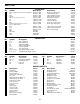
PARTS LIST RESISTORS Qty 11 1 1 2 8 1 1 1 17 1 1 1 1 2 1 1 Symbol Description Color Code Part # R15, 23, 26, 29, 32, 35, 38, 43, 46, VR6-7 R9 R22 R4, R2 R8, 12, 13, 14, 16, 18, 19, 17 R1 R3 R20 R7, 24, 25, 27, 28, 30, 31, 33, 34, 36, 37, 39-42, 44, 45 R10 R11 R21 VR4 VR1, VR2 VR5 VR3 150Ω 5% 1/4W 200Ω 5% 1/4W 470Ω 5% 1/4W 470Ω 5% 1/2W 1kΩ 5% 1/4W 2.2kΩ 5% 1/4W 2.
GENERAL SPECIFICATIONS FOR MODEL XK-150 Power Supplies: • +1.25V to 15VDC @ .25 amp • -1.25 to -20VDC @ .25 amp • +5V + 5% @ .5 amp • 30V AC center tapped at 15VAC @ .25 amp. • Load regulator all DC supplies less than .2V no load to .25A • Line regulator all DC supplies less than .2V 105 to 135V • Hum and ripple all DC supplies less than .01V RMS • Short protection all DC supplies-Internal IC thermal cutoff • Fuse - .
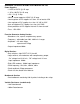
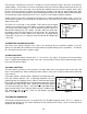
USERS DESCRIPTION OF FRONT PANEL CONTROL 11 12 13 14 15 16 17 10 9 18 8 19 7 20 6 21 5 22 4 23 3 24 2 25 1 26 29 1) 2) 3) 4) 5) 6) 7) 8) 9) 10) 11) 12) 13) 14) 15) 16) 17) 18) 19) 20) 21) 22) 23) 24) 25) 26) 27) 28) 29) 28 27 1kΩ undedicated potentiometer. Output Terminals for 1kΩ undedicated potentiometers. Output Terminals for -15V power supply. Gnd Terminals for the +/-15 variable power supply. Output Terminals for +15V power supply.
INTRODUCTION Congratulations on your purchase of the Elenco Model XK-150 Digital / Analog Trainer. This trainer is designed to simplify designing of digital and analog circuits. It contains most of the necessary test equipment needed to build and test these circuits. Your XK-150 has four basic trainers in a single package. They are, 4 independent power supplies, an analog trainer, a digital and a bredblock assembly trainer. We shall proceed in describing each trainer in the following sections.
TESTING THE XK-150 DIGITAL ANALOG TRAINER The following paragraphs give detailed instructions on testing the digital / analog trainer. Note that in the XK-150 trainer there are five major functions, (1) Power Supply (2) Logic Indicators (3) Function Generator (4) Logic Switches and (5) Data Switches. We shall proceed in testing out each section. POWER SUPPLY TESTING Plug the trainer into 120VAC outlet and set the power switch to the “ON” position. The red LED will light when the unit is on.
TESTING THE LOGIC INDICATOR FUNCTION There are eight logic indicators which you will be testing. Place a wire to the 5V terminal and touch the “0” LED logic indicator terminal. The “0” LED should light up. Remove the wire and the LED should go out. Do the same for the 1, 2, 3, 4, 5, 6 and 7 logic terminals. TESTING THE LOGIC SWITCHES There are two logic switches and four conditions to be tested. Connect a wire from the “A” terminal to the “7” LED logic indicator terminal.
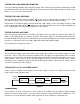
AC TO DC CONVERTER The AC to DC converter consists of diodes D1, D2 and capacitor C1. Transformer T1 has two secondary windings which are 180 degree out of phase. The AC output at each winding is shown in Figure 2A and 2B. Diodes are semiconductor devices that allow current to flow in one direction. The arrow in Figure 3 points to the direction current will flow. Only when the transformer voltage is positive will current flow through the diodes. Figure 3 shows the simplest possible rectifier circuit.
Transistor Q5 is called the pass transistor. It controls the current reaching the output. Transistor Q3 and Q4 are emitter followers. Their function is to raise the impedance of the pass transistor. Note that transistor Q2, Q3, Q4, Q5 and resistor R1 form a close loop. Also note that the feedback to the base of Q2 is negative, that is, when the base of Q2 goes positive, the output at emitter Q5 goes negative.
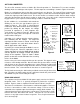
The XR-2206 is comprised of four functional blocks, a voltage controlled oscillator (VCO), an analog multiplier & sine shaper, a unity gain buffer amplifier and a set of current switches. The VCO actually produces an output frequency proportional to an input current. Across pins 5 and 6, two timing capacitor are switched between to give different frequency ranges. On pin 7, the 1MΩ variable resistor controls the actual frequency output.
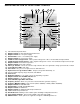
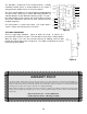
SCHEMATIC DIAGRAM -10-
Elenco Electronics, Inc. 150 W. Carpenter Avenue Wheeling, IL 60090 (847) 541-3800 http://www.elenco.com e-mail: elenco@elenco.