Catalog # 28-287 REV-C Revised 2008 753296
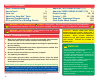
Table of Contents Basic Troubleshooting How to Use It Parts List About Your Snap Kits Parts Advanced Troubleshooting DO’s and DON’Ts of Building Circuits TM ! 1 2 3, 4 5, 6 7, 8 9 About the TWO-SPRING SOCKET (?1) 10 About the THREE-SPRING SOCKET (?Q) 11 Project Listings 12 - 14 Projects 1 - 303 15 - 126 Snap Kits Experiment Shapes 128 Other Radio Shack Projects 130 TM WARNING TO ALL PARTS WITH A ! SYMBOL - Moving parts. Do not touch the motor or fan during operation. Do not lean over the motor.
How To Use It The Radio Shack Snap Kits has 303 projects. They are simple to build and understand. TM To build each circuit, you have a power source block number B1 that needs two (2) “AA” batteries (not included with Snap Kits ). TM Snap Kits uses building blocks with snaps to build the different electrical and electronic circuits in the projects. Each block has a function: there are switch blocks, lamp blocks, battery blocks, different length wire blocks, etc.
Parts List (Colors and styles may vary) Symbols and Numbers Note: If you have model RS-303, then there are additional part lists in your other project manuals. Important: If any parts are missing or damaged in shipping, DO NOT RETURN TO RADIO SHACK. Call toll-free 1-800-THE-SHACK. Qty. ID 1 -3- Name Symbol Part # Qty. ID Name Symbol Part # Base Grid (11.0” x 7.
Parts List (Colors and styles may vary) Symbols and Numbers Note: If you have model RS-303, then there are additional part lists in your other project manuals. Important: If any parts are missing or damaged in shipping, DO NOT RETURN TO RADIO SHACK. Call toll-free 1-800-THE-SHACK. Qty. ID Name Symbol Part # 1 1 M1 Motor Fan 6SCM1 6SCM1F 1 D1 Red Light Emitting Diode (LED) 1 D2 1 Qty.
TM About Your Snap Kits Parts (Part designs are subject to change without notice). Note: If you have Model RS-303, there is additional information in your other project manual. A light bulb, such as in the 6V lamp (L2), contains a special wire that glows bright when a large electric current passes through it. Voltages above the bulb’s rating can burn out the wire. The base grid functions like the printed circuit boards found in most electronic products.
TM About Your Snap Kits Parts (continued) Some types of electronic components can be super-miniaturized, allowing many thousands of parts to fit into an area smaller that your fingernail. These “integrated circuits” (IC’s) are used in everything from simple electronic toys to the most advanced computers.
Advanced Troubleshooting (Adult supervision recommended) Radio Shack is not responsible for parts damaged due to incorrect wiring. If you suspect you have damaged parts, you can follow this procedure to systematically determine which ones need replacing: 1. 6V lamp (L2), motor (M1), speaker (SP), and battery holder (B1): Place batteries in holder and install bulb in lamp socket. Place the 6V lamp directly across the battery holder, it should light.
Advanced Troubleshooting (continued) (Adult supervision recommended) 11. Adjustable resistor (RV): Build project #204 but use the 1KΩ resistor (R2) in place of the photoresistor (RP). Turn on the slide switch (S1), the resistor control can turn the LED (D1) on and off. 12. 100μF (C4) and 470μF capacitor (C5): Build project #49, then press and release the press switch (S2). The LED (D1) should go off slowly. Replace the 470μF with the 100μF and the LED is only lit for about 4 seconds now. 13.
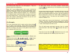
DO’s and DON’Ts of Building Circuits After building the circuits given in this booklet, you may wish to experiment on your own. Use the projects in this booklet as a guide, as many important design concepts are introduced throughout them. Every circuit will include a power source (the batteries), a resistance (which might be a resistor, lamp, motor, integrated circuit, etc.), and wiring paths between them and back.
About the TWO-SPRING SOCKET (?1) The two-spring socket (?1) just has two springs, and won’t do anything by itself. It is not used in any of the experiments. It was included to make it easy to connect other electronic components to your Snap Kits . It should only be used by advanced users who are creating their own circuits. TM There are many different types of electronic components and basic parts, like resistors and capacitors, that have a wide range of available values.
About the THREE-SPRING SOCKET (?Q) The three-spring socket (?Q) makes it easy to connect your own transistors (and other parts) to circuits by connecting them between the springs: The three-spring socket (?Q) just has three springs, and won’t do anything by itself. It is not used in any of the experiments. It was included to make it easy to connect other electronic components to your Snap Kits . It should only be used by advanced users who are creating their own circuits.
Project Listings Project # 1 2 3 4 5 6 7 8 9 10 11 12 13 14 15 16 17 18 19 20 21 22 23 24 25 26 27 28 29 30 31 32 33 34 Description Electric Light & Switch DC Motor & Switch Hear the Motor Adjusting Sound Level Lamp & Fan in Series Lamp & Fan in Parallel Light Emitting Diode One Direction for LED Conduction Detector Space War Alarm Combo Flying Saucer Decreasing Saucer Lift Two-Speed Fan The Fuse Musical Doorbell Momentary Alarm Alarm Circuit Laser Gun Space War Light Switch Paper Space War Light Police Si
Project Listings Project # 103 104 105 106 107 108 109 110 111 112 113 114 115 116 117 118 119 120 121 122 123 124 125 126 127 128 129 130 131 132 133 134 135 136 -13- Description Page # Pitch 54 Pitch (II) 54 Pitch (III) 54 Space War Sounds 55 Space War Sounds Controlled by Light 55 Adjustable Tone Generator 56 Photosensitive Electronic Organ 56 Electronic Cicada 56 Space War Radio 57 The Lie Detector 57 NPN Amplifier 58 PNP Amplifier 58 Sucking Fan 59 Blowing Fan 59 PNP Collector 59 PNP Emitter 59 NPN C
Project Listings Project # 205 206 207 208 209 210 211 212 213 214 215 216 217 218 219 220 221 222 223 224 225 226 227 228 229 230 231 232 233 234 235 236 237 238 Description Page # Motor Rotation 88 Motor Delay Fan 88 Motor Delay Fan (II) 88 High-pitch Bell 89 Steamship 89 Wet Finger Detector 89 Motor-activated Burglar Alarm 90 Light-activated Burglar Alarm 90 Spacey Fan 90 LED Fan Rotation Indicator 91 Space War Sounds with LED 91 Photoresistor Control 92 Sound Mixer Fan Driver 92 Electric Fan Stopped by
Project #1 Electric Light & Switch OBJECTIVE: To show how electricity is turned “ON” or “OFF” with a switch. Build the circuit shown on the left by placing all the parts with a black 1 next to them on the base first. Then, assemble parts marked with a 2. Install two (2) “AA” batteries (not included) into the battery holder (B1) and screw the bulb into the lamp socket (L2) if you have not done so already.
Project #3 Hear the Motor OBJECTIVE: To show how a motor works. Place the fan on the motor (M1). Press the press switch (S2) and listen to the motor. Why does the motor make sound? A motor uses magnetism to convert electrical energy into mechanical spinning motion. As the motor shaft spins around it connects/ disconnects several sets of electrical contacts to give the best magnetic properties. As these contacts are switched, an electrical disturbance is created, which the speaker (SP) converts into sound.
Project #5 Lamp & Fan in Series OBJECTIVE: To show how a lamp can indicate when a fan is running. Build the circuit shown on the left by placing all the parts with a black 1 next to them on the base first. Then, assemble parts marked with a 2. Finally, place the fan blade on the motor (M1). When you turn on the slide switch (S1), the fan will spin and the lamp (L2) should turn on. The fan will take a while to start turning due to inertia.
Project #7 Light Emitting Diode OBJECTIVE: To show how a resistor and LED are wired to emit light. Build the circuit shown on the left by placing all the parts with a black 1 next to them on the board first. Then, assemble parts marked with a 2. When you turn on the slide switch (S1), current flows from the batteries (B1) through the switch, through the resistor (R1), through the LED (light emitting diode) (D1) and back to the battery. The closed (turned on) switch completes the circuit.
Project #9 Conduction Detector OBJECTIVE: To make a circuit that detects the conduction of electricity in different materials. Rebuild the circuit from project #7 but leave the on-off switch out as shown on the left. When you place a metal paper clip across the terminals as shown in the picture on the left, current flows from the batteries (B1) through the resistor (R1), through the LED (D1), and back to the battery. The paper clip completes the circuit and current flows through the LED.
Project #11 Flying Saucer OBJECTIVE: To make a circuit that launches the fan blade to simulate a flying saucer. Rebuild the circuit from project #2, but reverse the polarity on the motor (M1) so the negative (–) on the motor goes to the positive (+) on the battery. When you turn on the slide switch (S1), the motor will slowly increase in speed. When the motor has reached maximum rotation, turn the slide switch off. The fan blade should rise and float through the air like a flying saucer.
Project #13 Two-Speed Fan OBJECTIVE: To show how switches can increase or decrease the speed of an electric fan. Build the circuit shown on the left by placing all the parts with a black 1 next to them on the board first. Then, assemble parts marked with a 2. Finally, add the 2-snap wires that are marked for level 3. ! WARNING: Moving parts. Do not touch the fan or motor during operation.
Project #15 Musical Doorbell OBJECTIVE: To show how an integrated circuit can be used as a musical doorbell. Build the circuit shown on the left. When you turn on the slide switch (S1), the music integrated circuit (U1) may start playing one song then stop. Each time you press the press switch “doorbell button” (S2) the song will play again and stop. Even if you let go of the press switch, the integrated circuit keeps the song playing until it has reached the end of the song.
Project #17 Alarm Circuit OBJECTIVE: To show how an integrated circuit can be used to make real alarm sounds. Build the circuit shown on the left by placing all the parts with a black 1 next to them on the board first. Then, assemble parts marked with a 2. When you turn on the slide switch (S1), the integrated circuit (U2) should start sounding a very loud alarm sound. This integrated circuit is designed to sweep through all the frequencies so even hard of hearing people can be warned by the alarm.
Project #19 Space War OBJECTIVE: To introduce you to the space war integrated circuit and the sounds it can make. Build the circuit shown on the left, which uses the space war integrated circuit (U3). Activate it by turning on the slide switch (S1) or pressing the press switch (S2), do both several times and in combination.
Project #22 Light Police Siren OBJECTIVE: To build a police siren that is controlled by light. Build the circuit shown on the left by placing all the parts with a black 1 next to them on the board first. Then, assemble parts marked with a 2. Finally, insert the parts with a 3 last on level 3. Cover the photoresistor (RP) and turn on the slide switch (S1). A police siren with music is heard for a while and stops, then you can control it by covering or uncovering the photoresistor.
Project #27 The Transistor OBJECTIVE: To compare transistor circuits. ! WARNING: Moving parts. Do not touch the fan or motor during operation. Place the fan on the motor (M1) and turn on the slide switch (S1) - nothing happens. Press the press switch (S2), the lamp (L2) lights dimly and the motor spins. The lamp will be brighter if you remove the fan from the motor. The NPN transistor (Q2) uses the lamp current to control the motor current.
Project #31 Sound Mixer OBJECTIVE: To connect two sound IC’s together. In the circuit, the outputs from the alarm and music IC’s are connected together. Build the circuit shown and then place the alarm IC (U2) directly over the music IC (U1), resting on two 1-snaps and a 2-snap. Turn on the slide switch (S1) and you will hear a siren and music together while the lamp (L2) varies in brightness.
Project #35 Space Battle OBJECTIVE: To show another way of using the space war integrated circuit. Build the circuit shown on the left, which is based on the circuit in the Space War project #19. Turn on the slide switch (S1) and you will hear exciting sounds, as if a space battle is raging! The motor (M1) is used here as a 3-snap wire, and will not spin. Project #37 Periodic Sounds OBJECTIVE: To build a circuit with light and sound that change and repeat.
Project #39 Motor-controlled Sounds OBJECTIVE: circuits. To show how motion can trigger electronic This circuit is controlled by spinning the motor (M1) with your hands. Turn on the slide switch (S1). A police siren is heard and then stops. Spin the motor and it will play again. Note, however, that music can be heard faintly in the background of the siren.
Project #44 Light-controlled Flicker OBJECTIVE: To make a circuit that uses light to control the blinking of another light. This circuit does not use the noisy speaker it uses a nice quiet LED (D1). Turn on the slide switch (S1), the LED flickers. Wait a few seconds, and then cover the photoresistor (RP), and the flicker stops. The flicker is controlled by the photoresistor; uncover it and the flicker resumes. People that are deaf need lights to tell them when a doorbell is ringing.
Project #46 Slow Off Switch OBJECTIVE: To learn about a device that is used to delay actions in electronics. Build the circuit and press the press switch (S2). You see that the LED (D1) turns off slowly after you release the switch. This delay in turning off the LED is caused by the 470μF capacitor (C5). Capacitors can store electricity and are used to delay changes in voltage. They can block unchanging voltages while passing fastchanging voltages.
Project #49 Auto-Off Night Light OBJECTIVE: To learn about one device that is used to delay actions in electronics. When you turn on the slide switch (S1) the first time, the light will come on and very slowly get dimmer and dimmer. If you turn the slide switch off and back on after the light goes out, it will NOT come on again. The 470μF capacitor (C5) has charged up and the NPN transistor amplifier (Q2) can get no current at its input to turn it on.
Project #51 Reflection Detector OBJECTIVE: To detect if a mirror is present. Build the circuit on the left. Place it where there won’t be any room light hitting the photoresistor (RP) (such as in a dark room or under a table), and then turn it on. The 6V lamp (L2) will be bright but there should be little or no sound. Take a small mirror and hold it over the lamp and photoresistor. You should hear sound now.
Project #53 Flashing Laser Light with Sound OBJECTIVE: To build the circuit used in a toy laser gun with flashing laser light and trigger. When you press the press switch (S2), the integrated circuit (U2) should start sounding a very loud laser gun sound. The red LED (D1) will flash simulating a burst of laser light. You can shoot long repeating laser burst, or short zaps by tapping the trigger switch.
Project #55 Spinning Rings OBJECTIVE: To build an electronic spinner. Setup: Cut out the disc on page #49 that looks like the one shown here. Using Scotch tape, attach the disc with the printed side up on the top of the fan blade. Place the blade on the motor (M1) as shown on the left and below. When the press switch (S2) is pressed, the arcs will turn into colored rings with a black background. Notice how the color drops in brightness when it is stretched to make a complete circle.
Project #57 Race Game OBJECTIVE: Build an electronic game for racing. Cut this shape from page 128 in this manual and tape it to the speaker. ! WARNING: Moving parts. Do not touch the fan or motor during operation. Project #58 Modify project #56 by adding the pointer as shown on the left. The paper should be cut from page 128 and taped high enough on the speaker (SP) so the pointer will stick over the fan with paper. Bend the pointer at a right angle as shown on the left.
Project #59 Spin Draw OBJECTIVE: To produce circular artistic drawings. Rebuild the simple motor connection as shown on the left. This is the same setup as project #57. Setup: Cut out a circular piece of thin cardboard from the back of an old spiral notebook or note pad. Use the fan blade as a guide. Place the fan on the cardboard and trace around it with a pencil or pen. Cut the cardboard out with scissors and tape it to the fan blade.
Project #61 Speaker Static OBJECTIVE: To learn about the speaker. Turn the slide switch (S1) on and off several times. You hear static from the speaker (SP) when you first turn on the switch, but hear nothing after it is left on. The speaker uses electromagnetism to create changes in air pressure, which your ears feel and interpret as sound. Think of the speaker as creating pressure waves in the air just like waves in a pool.
Project #64 The Transistor (V) OBJECTIVE: To compare transistor circuits. Place the fan on the motor (M1) and turn on the slide switch (S1), then compare this circuit to project #27. Press the press switch (S2), the lamp (L2) doesn’t light now, but the motor still spins. The lamp is dark because the 100Ω resistor (R1) limits the current through it. The NPN transistor (Q2) uses the small lamp current to create a large current that spins the motor.
Project #67 Simple Rectifier OBJECTIVE: To convert a changing voltage into a constant voltage. Turn on the slide switch (S1) and the LED (D1) lights; it will not be very bright so turn off the room lights or hold your fingers around it to see it better. Press the press switch (S2) several times slowly; the LED and lamp (L2) go on and off. Press the press switch many times quickly - the lamp still goes on and off but the LED stays on.
Project #69 Space War Siren OBJECTIVE: To combine effects from the space war and alarm integrated circuits. Build the circuit shown on the left and turn on the slide switch (S1). Press and hold the press switch (S2) to make the lamp (L2) brighter. Project #70 Sunrise Light OBJECTIVE: To learn about one device that is used to delay actions in electronics. Cover the photoresistor (RP) and turn on the slide switch (S1). The LED (D1) is off, but if you wait a long time then it will eventually light up.
Project #71 Light-controlled Lamp OBJECTIVE: To turn a lamp on and off using light. Cover the unit, turn the slide switch (S1) on, and notice that the lamp (L2) is off after a few seconds. Place the unit near a light and the lamp turns on. Cover the photoresistor (RP) and place it near the light again. The lamp will not turn on. The resistance of the photoresistor decreases as the light increases. The low resistance acts like a wire connecting point C to the positive (+) side of the battery (B1).
Project #74 Light-controlled LED OBJECTIVE: To control an LED using light. Cover the unit, turn the slide switch (S1) on, and notice that the LED (D1) is on for a few seconds and then goes off. Place the unit near a light and the LED will light. Cover the photoresistor (RP) and place it near the light again. The LED will not turn on. The resistance of the photoresistor decreases as the light increases. Project #75 Motor-controlled Time Delay LED OBJECTIVE: To control an LED using a motor.
Project #77 Space War Flicker LED OBJECTIVE: To flash an LED using the space war IC. Build the circuit shown on the left. The circuit uses the alarm IC (U2) and space war IC (U3) to flash the LED (D1). Turn the slide switch (S1) on and the LED starts flashing. Project #79 Project #78 Human Space War OBJECTIVE: To use your body to control the space war IC. Wet your fingers with some water or saliva and touch them across points A and B several times to hear some space war sounds.
Project #80 Fan Blade Storing Energy OBJECTIVE: To show that the fan blade stores energy. Place the fan on the motor (M1). Hold down the press switch (S2) for a few seconds and then watch the LED (D1) as you release the switch. The LED lights briefly but only after the batteries (B1) are disconnected from the circuit. Do you know why the LED lights? It lights because the mechanical energy stored in the fan blade makes the motor act like a generator.
Project #83 Fun with the Alarm IC OBJECTIVE: To show some new ways of using the alarm IC. Place the fan on the motor (M1) and turn on the slide switch (S1). The lamp (L2) lights, the motor spins, and you hear a machine gun sound (with music in background). Thoroughly cover the photoresistor (RP) with your hand and the sound becomes a siren. After a while the sound will stop, hold down the press switch (S2) and the sound resumes. ! Project #84 WARNING: Moving parts.
Project #86 Music Alarm Combo OBJECTIVE: To combine the sounds from the music and alarm integrated circuits. Build the circuit shown and then place the alarm IC (U2) directly over the music IC (U1), resting on the three 1-snaps. Turn on the slide switch (S1) and you will hear a siren and music together. After a few seconds, covering the photoresistor (RP) will stop the music (but the siren continues). Project #87 Bomb Sound OBJECTIVE: Build a circuit that sounds like a bomb dropping.
Project #89 Motor Sounds Combo OBJECTIVE: To connect multiple devices together. In the circuit, the outputs from the alarm IC (U2) and music IC (U1) are connected together. Build the circuit shown and then place the alarm IC directly over the music IC, resting on two 1-snaps and a 2-snap. Turn on the slide switch (S1) and you will hear a siren and music together while the lamp (L2) varies in brightness. Press the press switch (S2) and the fan spins, while the sound may not be as loud.
Project #91 Fan Detector OBJECTIVE: To make a circuit that detects if the fan is on the motor. Press the press switch (S2). If the fan is off the motor (M1) (or flies off) then the LED (L1) will light. It takes a lot of current to spin the motor when the fan is on it, and the voltage drops because the batteries (B1) cannot supply enough. When the fan flies off, the current drops and the voltage rises.
Project #93 Capacitor Photo Control OBJECTIVE: To learn about a device that is used to delay actions in electronics. Turn on the slide switch (S1) and press the press switch (S2). If there is light on the photoresistor (RP), then the LED (D1) will stay on for a long time after you release the press switch. The energy stored in the 470μF capacitor (C5) keeps the controlling current to the NPN transistor (Q2) on even though the press switch was turned off.
Project #95 Photo Space War with LED OBJECTIVE: To build a circuit that uses a programmed sound IC. Turn the slide switch (S1) on, a space war sound plays and the LED (D1) flashes. Press the press switch (S2) to change the sound. If the photoresistor (RP) is covered, then the sound may stop. Shine light on it and action resumes. See how many sounds are programmed into the space war sound IC (U3). Project #96 Alarm Rectifier OBJECTIVE: To convert a changing voltage into a constant voltage.
Project #97 Light-controlled Alarm OBJECTIVE: To show how light is used to turn an alarm. The alarm will sound, as long as light is present. Slowly cover the photoresistor (RP), and the volume goes down. If you turn off the lights, the alarm will stop. The amount of light changes the resistance of the photoresistor (less light means more resistance). The photoresistor and transistor (Q2) act like a dimmer switch, adjusting the voltage applied to the alarm.
Project #99 Lamp & Fan Independent OBJECTIVE: To show how switches allow circuits to operate independently even though they have the same power source. This circuit combines projects #1, #2, and #6 into one circuit. Build the circuit and place the fan on the motor (M1). Depending on which of the switches (S1 or S2) are on, you can turn on either the lamp (L2) (project #1), the motor (M1) (project #2), or both together (project #6). ! WARNING: Moving parts. Do not touch the fan or motor during operation.
Project #102 Automatic Street Lamp OBJECTIVE: To show how light is used to control a street lamp. Press the press switch (S2) on and set the adjustable resistor (RV) so the lamp (L2) just lights. Slowly cover the photoresistor (RP) and the lamp brightens. If you place more light at the photoresistor the light dims. This is an automatic street lamp that you can turn on by a certain darkness and turn off by a certain brightness.
Project #106 Space War Sounds OBJECTIVE: To build a circuit that produces multiple space war sounds. Turn the slide switch (S1) to the OFF position. Press the press switch (S2) down and a space sound will be played. If you hold the press switch down the sound repeats. Press the press switch again and a different sound is played. Keep pressing the press switch to hear all the different sounds. Next, turn the slide switch to ON position. One of the sounds will be played continuously.
Project #108 Adjustable Tone Generator OBJECTIVE: To show how resistor values change the frequency of an oscillator. Turn on the slide switch (S1), the speaker (SP) will sound and the LED (D1) will light. Adjust the adjustable resistor (RV) to make different tones. In an oscillator circuit, changing the values of resistors or capacitors can vary the output tone or pitch. Project #109 Photosensitive Electronic Organ OBJECTIVE: To show how resistor values change the frequency of an oscillator.
Project #111 Space War Radio OBJECTIVE: To transmit Space War sounds to a AM radio. Place the circuit next to an AM radio. Tune the radio so no stations are heard and turn on the slide switch (S1). You should hear the space war sounds on the radio. The red LED (D1) should also be lit. Adjust the variable capacitor (CV) for the loudest signal. You have just performed the experiment that took Guglielmo Marconi (who invented the radio) a lifetime to invent.
Project #113 NPN Amplifier OBJECTIVE: To compare transistor circuits. There are three connection points on an NPN transistor (Q2), called base (marked B), emitter (marked E), and collector (marked C). When a small electric current flows from the base to the emitter, a larger (amplified) current will flow from the collector to the emitter. Build the circuit and slowly move up the adjustable resistor (RV) control. When the LED (D2) becomes bright, the lamp (L2) will also turn on and will be much brighter.
Project #115 Sucking Fan OBJECTIVE: To adjust the speed of a fan. Build the circuit, and be sure to orient the motor (M1) with the positive (+) side down as shown. Turn it on, and set the adjustable resistor (RV) for the fan speed you like best. If you set the speed too fast, then the fan may fly off the motor. Due to the shape of the fan blades and the direction the motor spins, air is sucked into the fan and towards the motor. Try holding a piece of paper just above the fan to prove this.
Project #119 NPN Collector Project #120 NPN Emitter OBJECTIVE: To compare transistor circuits. OBJECTIVE: To compare transistor circuits. Compare this circuit to that in project #117, it is the NPN transistor (Q2) version and works the same way. Which circuit makes the lamp (L2) brighter? (They are about the same because both transistors are made from the same materials). Compare this circuit to that in project #118. It is the NPN transistor (Q2) version and works the same way.
Project #123 Buzzing in the Dark Project #124 Touch Buzzer OBJECTIVE: To make a circuit that buzzes when the lights are off. OBJECTIVE: To build a human buzzer oscillator. This circuit makes a highfrequency screaming sound when light shines on the photoresistor (RP), and makes a buzzing sound when you shield the photoresistor.
Project #128 Radio Music Alarm OBJECTIVE: To build a radio music alarm. You need an AM radio for this project. Build the circuit on the left and turn on the slide switch (S1). Place it next to your AM radio and tune the radio frequency to where no other station is transmitting. Then, tune the variable capacitor (CV) until your music sounds best on the radio. Now connect a 4-snap wire between X & Y on the drawing, the music stops.
Project #134 Fire Fan Symphony OBJECTIVE: To combine sounds from the music, alarm, and space war integrated circuits. Build the circuit shown, note that in some places parts are stacked on top of each other. Turn it on and press the press switch (S2) several times and wave your hand over the photoresistor (RP) to hear the full spectrum of sounds that this circuit can create. Have fun! ! Project #135 WARNING: Moving parts. Do not touch the fan or motor during operation.
Project #136 Police Car Symphony OBJECTIVE: To combine sounds from the integrated circuits. Build the circuit shown and note that in some places parts are stacked on top of each other. Turn it on and press the press switch (S2) several times and wave your hand over the photoresistor (RP) to hear the full spectrum of sounds that this circuit can create.
Project #138 Static Symphony OBJECTIVE: To combine sounds from the integrated circuits. Project #139 Static Symphony (II) OBJECTIVE: See project #138. Build the circuit shown. Note that in some places parts are stacked on top of each other. Turn it on and press the press switch (S2) several times and wave your hand over the photoresistor (RP) to hear the full spectrum of sounds that this circuit can create. Have fun! Project #140 Capacitors in Series OBJECTIVE: To compare types of circuits.
Project #142 Current Controllers Project #143 NPN Dark Control OBJECTIVE: To compare types of circuits. OBJECTIVE: To compare transistor circuits. Build the circuit and turn on the slide switch (S1), the LED (D1) will be lit. To increase the LED brightness, press the press switch (S2). To decrease the LED brightness, turn off the slide switch. With the slide switch on, the 5.1KΩ resistor (R3) controls the current.
Project #146 Whining Fan OBJECTIVE: To make different sounds. Build the circuit on the left. Turn on the slide switch (S1) and move the setting on the adjustable resistor (RV) across its range. You hear a high-pitch whine and the fan spins. ! Project #147 Light Whining OBJECTIVE: To make different sounds. WARNING: Moving parts. Do not touch the fan or motor during operation. Project #148 More Light Whining OBJECTIVE: To make different sounds.
Project #150 Current Equalizing OBJECTIVE: To compare types of circuits. Turn on the slide switch (S1) and the two LED’s (D1 & D2) will have the same current. When connected in series, all components will have equal electric current through them. Project #151 Lazy Fan OBJECTIVE: To build a fan that doesn’t work well. Project #152 Laser Light OBJECTIVE: To build a simple laser. Press the press switch (S2) and the fan will be on for a few turns.
Project #153 Whiner OBJECTIVE: To build a circuit that makes a loud whine. Build the circuit, turn it on, and move the setting on the adjustable resistor (RV). It makes a loud, annoying, whining sound. The green LED (D2) appears to be on, but it is actually flashing at a very fast rate. Project #154 Hummer OBJECTIVE: To show how adding capacitance reduces frequency. Project #155 Adjustable Metronome Project #156 Quiet Flasher OBJECTIVE: flashlight.
Project #157 Hissing Foghorn OBJECTIVE: To build a transistor oscillator that can make a foghorn sound. Build the circuit on the left and move the adjustable resistor (RV) setting. Sometimes it will make a foghorn sound, sometimes it will make a hissing sound, and sometimes it will make no sound at all. Project #158 Hissing & Clicking OBJECTIVE: To build an adjustable clicking oscillator. Project #159 Video Game Engine Sound OBJECTIVE: To build a human oscillator.
Project #160 Make Your Own Battery OBJECTIVE: To demonstrate how batteries can store electricity. Build the circuit, then connect points Y & Z (use a 2-snap wire) for a moment. Nothing appears to happen, but you just filled up the 470μF capacitor (C5) with electricity. Now disconnect Y & Z and instead touch a connection between X & Y. The green light emitting diode (D2) will be lit and then go out after a few seconds as the electricity you stored in it is discharged through the diode and resistor (R2).
Project #163 Tone Generator OBJECTIVE: To build a high-frequency oscillator. Build the circuit and turn it on. You hear a high-frequency sound. Project #164 Tone Generator (II) OBJECTIVE: To lower the frequency of a tone by increasing circuit capacitance. Replace the 0.02μF capacitor (C1) with the larger 0.1μF capacitor (C2). You now hear a low frequency sound, due to more capacitance. Project #165 Tone Generator (III) OBJECTIVE: To raise the frequency of a tone by decreasing circuit resistance.
Project #166 More Tone Generator OBJECTIVE: To build a middle-frequency oscillator. Build the circuit, as the name suggests this circuit is similar to that in project #163. Turn it on, you hear a middle-frequency sound. Project #167 More Tone Generator (II) OBJECTIVE: To raise the frequency of a tone by decreasing circuit resistance. Replace the 0.02μF capacitor (C1) with the larger 10μF capacitor (C3). You hear a low frequency clicking sound, due to more capacitance.
Project #169 Music Radio Station OBJECTIVE: To create music and transmit it to a radio. Project #170 Alarm Radio Station OBJECTIVE: To create music and transmit it to a radio. You need an AM radio for this project. Build the circuit shown on the left and turn on the slide switch (S1). Place it next to your AM radio and tune the radio frequency to where no other station is transmitting. Then, tune the adjustable capacitor (CV) until your music sounds best on the radio.
Project #172 Motor & Lamp by Sound OBJECTIVE: To control a motor using light. Turn the slide switch (S1) on, the motor (M1) spins and the lamp (L2) lights. As you move your hand over the photoresistor (RP), the motor slows. Now place your finger onto the photoresistor to block the light. The motor slows down. In a few seconds, the motor speeds up again. ! Project #173 WARNING: Moving parts. Do not touch the fan or motor during operation.
Project #174 Changing Siren OBJECTIVE: To build a siren that changes after a few seconds. When you turn on the press switch (S2), the integrated circuit (U2) will make a loud siren sound and the LED (D1) will light. After a few seconds the sound will change to a different siren. Leave the circuit off for a while to recharge the first siren. Project #175 Symphony of Sounds OBJECTIVE: To combine sounds from the music, alarm, and space war integrated circuits. Build the circuit shown.
Project #176 Transistor Amplifiers OBJECTIVE: To learn about the most important component in electronics. When you place one or more fingers across the two snaps marked X & Y you will notice the light comes on. The two transistors are being used to amplify the very tiny current going through your body to turn on the LED (D1). Transistors are actually electrical current amplifiers. The PNP transistor (Q1) has the arrow pointing into the transistor body.
Project #179 Auto-off Night Light (III) OBJECTIVE: To learn about one device that is used to delay actions in electronics. When you turn on the slide switch (S1) the first time the LED (D1) will come on and slowly get dim. If you turn the slide switch off and back on after the LED goes out, it will NOT come on again. The 100μF capacitor (C4) has charged up and the NPN transistor amplifier (Q2) can get no current at its input to turn it on. This circuit would make a good night-light.
Project #181 Morse Code Generator OBJECTIVE: To make a Morse code generator and learn to generate code. When you press the press switch (S2) you will hear a tone. By pressing and releasing the press switch you can generate long and short tones called Morse code. For International code, a short tone is represented by a “+”, and a long tone by a “–”. See the chart below for letter or number followed by code.
Project #186 Mind Reading Game OBJECTIVE: To make an electronic game of mind reading. Shorting Bar for W, X, Y, or Z. Build the circuit shown on the left. It uses two (2) 2-snap wires as shorting bars. Setup: Player 1 sets up by placing one shorting bar under the paper on row A, B, C, or D. Player 2 must NOT know where the shorting bar is located under the paper. Paper Sheet to hide position of shorting bar.
Project #187 Paper Sheet to hide position of shorting bar. Shorting Bar for W, X, Y, or Z. Enhanced Quiet Zone Game OBJECTIVE: Make and play the electronic game of “Quiet Zone”. Use the circuit from project #186, but place three (3) 2-snap wires (“shorting bars”) under paper as shown on left. Setup: Player 1 sets the “Quiet Zone” by placing three (3) shorting bars under the paper on row A, B, C, or D, leaving only one open. Player 2 must NOT know where the shorting bars are located under the paper.
Project #189 Two-Finger Touch Lamp OBJECTIVE: To show that your body can be used as an electronic component. Build the circuit on the left. You’re probably wondering how it can work, since one of the points on the NPN transistor (Q2) is unconnected. It can’t, but there is another component that isn’t shown. That component is you. Touch points X & Y with your fingers. The LED (D1) may be dimly lit. The problem is your fingers aren’t making good enough electrical contact with the metal.
Project #191 Space Battle OBJECTIVE: To show how sound can turn “ON” an electronic device. Project #192 Space Battle (II) OBJECTIVE: To show how light can turn “ON” an electronic device. Build the circuit shown on the left. Activate the circuit by turning on the slide switch (S1) or pressing the press switch (S2), do both several times and in combination.
Project #195 Storing Electricity OBJECTIVE: To store electricity in a capacitor. Turn the slide switch (S1) on and connect points A & B with a 2-snap wire. The green LED (D2) will flash and the 470μF capacitor (C5) will be charged with electricity. The electricity is now stored in the capacitor. Disconnect points A & B. Connect points B & C and there will be a flash from the 6V lamp (L2). The capacitor discharges through the resistor (R1) to the base of the NPN transistor (Q2).
Project #198 Fire Engine Symphony OBJECTIVE: To combine sounds from the music, alarm, and space war integrated circuits. Build the circuit shown. Turn it on, press the press switch (S2) several times, and wave your hand over the photoresistor (RP) to hear the full spectrum of sounds that this circuit can create. Have fun! Project #199 Light Dimmer OBJECTIVE: To build a light dimmer. Press the press switch (S2) to complete the current's path flow.
Project #200 Motion Detector OBJECTIVE: Build a circuit that detects motion. Set the adjustable resistor (RV) to the center position. Turn the slide switch (S1) on and the LED (D1) lights. Wave your hand over the photoresistor (RP) and the LED turns off and on. The resistance changes as the amount of light strikes the photoresistor. As the light decreases, the resistance increases. The increased resistance lowers the voltage at the base of the NPN transistor (Q2).
Project #202 Oscillator 0.5 - 30Hz OBJECTIVE: To build a 0.5Hz - 30Hz oscillator that will light an LED. Set the adjustable resistor (RV) to the bottom position and then turn the slide switch (S1) on. The LED (D1) will start flashing at a frequency of 0.5Hz (once every two seconds). Slowly adjust the adjustable resistor and the LED flashes faster. As the frequency increases, the LED flashes faster. Eventually, the LED flashes so fast, it looks like it is on all of the time.
Project #205 Motor Rotation OBJECTIVE: To show how voltage polarity affects a DC motor. Place the fan onto the motor (M1). Press the press switch (S2), the fan rotates clockwise. When you connect the positive (+) side of the battery (B1) to the positive (+) side of the motor, it spins clockwise. Release the press switch and turn on the slide switch (S1). Now the fan spins the other way. The positive (+) side of the battery is connected to the negative (–) side of the motor.
Project #208 High-pitch Bell OBJECTIVE: To build a high pitch bell. Build the circuit shown and press the press switch (S2). The circuit starts to oscillate. This generates the sound of a high pitch bell. Project #209 Steamship OBJECTIVE: To generate the sound of a steamship. Using the circuit in project #208, connect the 0.1μF capacitor (C2) across the 0.02μF capacitor (C1). Press the press switch (S2). The circuit now generates the sound of a steamship.
Project #211 Motor-activated Burglar Alarm OBJECTIVE: To build a motor-activated alarm. Place the circuit into a room you want guarded. Wind a piece of string around the axis of the motor (M1) so when you pull it the axes spins. Connect the other end of the string to a door or window. Turn the slide switch (S1) on and wait for the sound to stop. If a thief comes in through the door or window the string pulls and the axis spins. This will activate the sound.
Project #214 LED Fan Rotation Indicator OBJECTIVE: To build an LED fan rotation indicator. Place the fan onto the motor (M1). Turn the slide switch (S1) on. The fan rotates clockwise, the green LED (D2) and the lamp light (L2). When you connect the positive (+) side of the battery (B1) to the positive (+) side of the motor, it spins clockwise. Turn the switch off and press the press switch (S2). Now the fan spins the other way and the red LED (D1) and lamp light.
Project #216 Photoresistor Control OBJECTIVE: To use a photoresistor to control the brightness of an LED. In this circuit, the brightness of the LED (D1) depends on how much light shines directly on the photoresistor (RP). If the photoresistor were held next to a flashlight or other bright light, then the LED would be very bright. The resistance of the photoresistor decreases as more light shines on it.
Project #218 Electric Fan Stopped by Light OBJECTIVE: To show how light can control a motor. Turn on the slide switch (S1) and set the adjustable resistor (RV) control so the motor (M1) just starts spinning. Slowly cover the photoresistor (RP) and the motor spins faster. By placing more light over the photoresistor, the motor slows down. The fan will not move on most settings of the resistor, because the resistance is too high to overcome friction in the motor.
Project #220 Start-stop Delay OBJECTIVE: To start and stop a motor with light. Place the fan on the motor (M1). Turn on the slide switch (S1), the motor starts spinning. As you move your hand over the photoresistor (RP), the motor slows. Now place a finger on top of the photoresistor to block the light. The motor slows down. In a few seconds the motor speeds up again. ! Project #221 WARNING: Moving parts. Do not touch the fan or motor during operation.
Project #222 Mail Notifying Electronic Bell OBJECTIVE: To build a circuit to indicate if you have mail by sounding a tone. Turn on the slide switch (S1). If there is enough light on the photoresistor (RP), the speaker (SP) will not make any sound. Place your finger over the photoresistor and now the speaker sounds. The sound will stay on until you turn off the switch. A simple mail notifying system can be made using this circuit.
Project #225 Project #226 Lasting Doorbell Lasting Clicking OBJECTIVE: To build a doorbell that stays on for a while. Build the circuit at left, note that there is a 4-snap wire on layer 1 that is not connected to a 3-snap wire that runs over it on layer 3. Turn on the slide switch (S1), then press and release the press switch (S2). There is a doorbell sound that slowly fades away. When the press switch is pressed, the transistors (Q1 & Q2) are supplied with current for oscillation.
Project #229 Adjustable Time Delay Lamp Project #230 OBJECTIVE: To build a lamp that stays on for a while. Adjustable Time Delay Fan OBJECTIVE: To build a fan that stays on for a while. Turn on the slide switch (S1) and press the press switch (S2). The lamp (L2) stays on for a while after you release the press switch. You can change the delay time with the adjustable resistor (RV). Replace on battery holder (B1) with a 3snap and replace the lamp (L2) with the motor (M1), be sure to put on the fan.
Project #233 Adjustable Project #234 Time Delay Adjustable Time Delay Fan (II) Lamp (II) OBJECTIVE: To build a lamp that stays on for a while. Turn on the slide switch (S1) and press the press switch (S2). The lamp (L2) stays on for a few seconds after you release the press switch. You can change the delay time with the adjustable resistor (RV). OBJECTIVE: To build a fan that stays on for a while.
Project #237 This OR That OBJECTIVE: To introduce you to the OR concept of electronic wiring. Build the circuit shown. Notice that if you turn on the slide switch (S1) OR press the press switch (S2) the LED (D1) lights up. There is no partially lit state here, the diode is either totally on or totally off. While this may seem very simple and boring, it represents an important concept in electronics.
Project #239 Neither This NOR That OBJECTIVE: To demonstrate the concept of a NOR circuit. Build the circuit on the left and test the combinations of the slide switch (S1) and press switch (S2). If you compare it to the OR circuit in project #237, you can see the LED (D1) lights in the opposite combinations of that circuit. Hence, we refer to it as a NOR circuit (short for “NOT this OR that”). Like the OR and AND, it is an important building block in computers.
Project #241 Music AND Gate OBJECTIVE: To build an AND gate. You will only hear music if you turn on the slide switch (S1) AND press the press switch (S2). This is referred to as an AND gate in electronics. This concept is important in computer logic. Example: If condition X AND condition Y are true, then execute instruction Z. Project #242 Lamp, Speaker & Fan in Parallel OBJECTIVE: To show the power drop of components connected in parallel. Leave the fan off the motor (M1).
Project #243 Light-controlled LED (II) OBJECTIVE: Build a circuit that turns an LED on and off if there is light present. When there is light on the photoresistor (RP), the LED (D1) will flicker. Shield the photoresistor from the light, the LED should turn off. Project #244 AM Radio OBJECTIVE: To build a one IC AM radio. Turn on the slide switch (S1) and adjust the variable capacitor (CV) for a radio station.
Project #245 Transistor AM Radio OBJECTIVE: To show the output of an AM radio. This AM radio circuit uses a transistor (Q2) in the amplifier that drives the speaker (SP). Turn on the slide switch (S1) and adjust the variable capacitor (CV) for a radio station, then adjust the loudness using the adjustable resistor (RV). Project #246 Antenna Storing Energy OBJECTIVE: To show that the antenna stores energy. Hold down the press switch (S2) and then watch the LED (D1) as you release the switch.
Project #247 Back EMF OBJECTIVE: To demonstrate how the motor works. ! WARNING: Moving parts. Do not touch the fan or motor during operation. The voltage produced by a motor when it is spinning is called its Back Electro-Motive-Force (Back EMF); this may be thought of as the motor’s electrical resistance. The motor’s Front Electro-Motive-Force is the force it exerts in trying to spin the shaft. This circuit demonstrates how the Back EMF increases and the current decreases as the motor speeds up.
Project #249 Electromagnet Delayer OBJECTIVE: To learn about the electromagnet. Build the circuit and turn it on. After a delay of about 2 seconds, the lamp (L2) will light but be dim. Replace your batteries if it does not light at all. Why does the electromagnet (M3) delay the lamp turn-on? The electromagnet contains a large coil of wire, and the batteries (B1) have to fill the coil with electricity before the lamp can turn on.
Project #251 Electromagnetism OBJECTIVE: related. To learn how electricity and magnetism are Put the iron core rod into the electromagnet (M3). Press the press switch (S2) and hold some iron objects near the electromagnet (M3), they will be attracted to it. By carrying the base grid around, you can use the electromagnet to pick up iron objects such as nails. Electricity and magnetism are closely related, and an electric current flowing in a coil of wire has a magnetic field just like a normal magnet.
Project #252 Electromagnetism & Compass OBJECTIVE: related. Magnetic Field Compass Project #253 To learn how electricity and magnetism are You need a compass for this project (not included). Use the circuit from project #251, with the iron core rod in the electromagnet (M3). You may want to use the slide switch (S1) in place of the press switch (S2), but only turn it on as needed or you will quickly drain your batteries.
Project #254 Electromagnet Tower OBJECTIVE: magnetism. To show how electricity can lift things using This circuit gives a dramatic demonstration of how the electromagnet can suck up a paper clip. Take a paper clip and straighten it out, then bend it in half. Drop it into the electromagnet (M3) center, and then press the press switch (S2) several times. The paper clip gets sucked into the center of the electromagnet and stays suspended there until you release the switch.
Project #256 Paper Clip Oscillator (II) OBJECTIVE: magnetism. To show how electricity can lift things using Take a paper clip and straighten it out, bend it in half, and place it into the electromagnet (M3) center. Turn on the slide switch (S1), and set the adjustable resistor (RV) control lever to the right. The paper clip gets sucked into the center of the electromagnet and stays suspended there. Move the adjustable resistor lever to the left, and the paper clip falls.
Project #258 Paper Clip Oscillator (IV) OBJECTIVE: magnetism. To show how electricity can lift things using Take a paper clip and straighten it out, bend it in half, and place it into the electromagnet (M3) center. Turn on the slide switch (S1), and set the adjustable resistor (RV) control lever to the right. The paper clip gets sucked into the center of the electromagnet and stays suspended there. Move the adjustable resistor lever to the left, and the paper clip falls.
Project #261 Siren Paper Clip Vibrator OBJECTIVE: To show how electricity can move things using magnetism. Take a paper clip and straighten it out, bend it in half, and place it into the electromagnet (M3) center. Turn on the slide switch (S1), and the paper clip should vibrate. Drop in Now press the press switch (S2), the paper clip is suspended in the air by the electromagnet and a siren alarm sounds. Straighten and bend paper clip Project #262 Alarm Paper Clip Vibrator OBJECTIVE: magnetism.
Project #264 Alarm Vibrator w/ LED OBJECTIVE: To show how electricity can move things using magnetism. Take a paper clip and straighten it out, bend it in half, and place it into the electromagnet (M3) center. Turn on the slide switch (S1), and the paper clip should vibrate and LED (D1) flashes. Drop in Now push the press switch (S2), the paper clip is sucked up by the electromagnet and a siren alarm sounds.
Project #266 Motor Oscillator OBJECTIVE: To experiment with oscillator circuits. This circuit flashes the lamp (L2) and turns the motor (M1) about once a second. Moving the control lever on the adjustable resistor (RV) makes these occur more or less often. This works with the fan on or off the motor. Nothing happens while the capacitor (C4) charges up through resistors RV and R4. Then the capacitor discharges in a burst that lights the lamp and turns the motor.
Project #269 Two-speed Motor Lights OBJECTIVE: To control the motor speed. Turn on the slide switch (S1), the motor (M1) spins and the lamp (L2) lights. Press the press switch (S2), the motor spins faster and the LED (D1) lights but the lamp is off. ! Project #270 WARNING: Moving parts. Do not touch the fan or motor during operation. Two-speed Motor Lights-Sound OBJECTIVE: To control the motor speed.
Project #271 Short-time Sound OBJECTIVE: To make a brief sound. Turn on the slide switch (S1) and you a siren sound for only a second or two, increase the light on the photoresistor (RP) to make it last longer. Project #272 Slow Light Dimmer OBJECTIVE: To show how capacitors delay circuit changes. Turn on the slide switch (S1) and the LED (D1) comes on if there is light on the photoresistor (RP).
Project #273 Fading Bomb Sound OBJECTIVE: To make a fading sound. Turn on the slide switch (S1), you hear a bomb sound that fades away as the 470μF capacitor (C5) charges up. Push the press switch (S2) to discharge the capacitor and make the sound loud again. Project #274 Fading Music Sound OBJECTIVE: To make a fading sound. Turn on the slide switch (S1), you hear music that fades away as the 470μF capacitor (C5) charges up.
Project #276 Sound & Lights OBJECTIVE: To show how the music IC can be used. Turn on the slide switch (S1), you hear sound from the speaker (SP) while the lamp (L2) and LED (D1) are bright. After the sound stops, only the LED will remain on. Press the press switch (S2) to restart the sound. Project #277 Music with Timer OBJECTIVE: To connect the music IC to a timer circuit. Turn on the slide switch (S1) and bulb (L2) lights. Press the press switch (S2) and the music IC (U1) plays and stops.
Project #278 Motor Tone Generator OBJECTIVE: To build a high-frequency oscillator. Build the circuit and set the adjustable resistor (RV) to the middle position. Turn on the slide switch (S1) and you hear a high-frequency sound from the speaker (SP). Move the adjustable resistor slightly to the left or right and the frequency changes. Quickly rotate the motor’s (M1) shaft back and forth and the frequency changes.
Project #282 Turn Off Timer OBJECTIVE: To build a circuit that turns off an LED for 4 seconds. Turn on the slide switch (S1). Pressing the press switch (S2) down increases the voltage at the base of Q1. This turns the Q1, Q2, and LED (D1) off as the capacitor (C4) charges up. As you release the press switch, the capacitor starts discharging through resistor R5. When the voltage from the discharging capacitor drops low enough, Q1,Q2, and the LED turns off for about 4 seconds.
Project #285 Alarm Timer OBJECTIVE: To connect the alarm IC to a timer circuit. Turn on the slide switch (S1) and the alarm may sound and slowly drift away as the lamp (L2) brightens. Press the press switch (S2) and the alarm sounds at full volume as the LED (D1) lights. Capacitor C5 is also charged. Release the press switch; the alarm IC (U2) still sounds because the voltage from the discharging C5 keeps Q1 and Q2 off.
Project #288 Space War Timer OBJECTIVE: To build a space war timer. Turn on the switch (S1) and the lamp (L2) lights and you hear the speaker (SP) sound. Now press the press switch (S2); the LED (D1) lights and the lamp turns off as the speaker sounds. You can change the length of time the speaker sounds by changing the values of C4 and R5. Project #289 Alarm Speed Adjuster OBJECTIVE: To change the speed of the alarm IC sound.
Project #290 The SCR OBJECTIVE: To use two transistors to make an SCR. The transistors (Q1 & Q2) are connected so when the base of Q2 goes high, both Q2 and Q1 turn on. They will remain on until the slide switch (S1) is turned off. Turn on the slide switch and the LED (D1) should not light. Now press the press switch (S2) and the LED lights. Turn the LED off by turning the slide switch off. The two transistors act as an electronic device called an SCR (Silicon Controlled Rectifier).
Project #294 LED Control Motor OBJECTIVE: To indicate when a motor is spinning using an LED. Place the fan on the motor (M1), turn on the slide switch (S1), and the LED (D1) lights but the motor does not spin. Pressing the press switch (S2) connects the motor to the battery (B1). The voltage across the LED drops, and the LED goes out. You can make a remote motor spinning indicator if the LED was wired to a different location. ! Project #295 WARNING: Moving parts.
Project #296 Light Oscillator OBJECTIVE: To control an oscillator circuit using light. Set the adjustable resistor (RV) to the middle position and then turn on the slide switch (S1). Wave your hand over the photoresistor (RP) and the sound changes. You can adjust the sensitivity by moving the adjustable resistor to a different position. Project #297 Sound, Light & Motor Stepper Circuit OBJECTIVE: To build a stepper circuit that powers a motor, speaker and LED.
Project #298 Blink & Beep OBJECTIVE: To build a circuit that blinks an LED and drives a speaker. Set the adjustable resistor (RV) to the far left and turn on the slide switch (S1). The LED (D1) lights and the speaker (SP) sounds once per second. Adjusting the adjustable resistor to the right increases the rate. Project #299 Blink & Beep (II) OBJECTIVE: To modify project #298 for a seven second delay and then a continuous sound. Replace the 10μF capacitor (C3) with the 100μF capacitor (C5) and the 0.
Project #301 Alarm Motor OBJECTIVE: To build a circuit where the alarm IC controls the fan speed. Place the fan on the motor and turn on the slide switch (S1). A machine gun sound is heard and the fan spins unevenly. The fan speed is being controlled by the alarm IC (U2). Now, press the press switch (S2) to control the motor directly, and the motor spins much faster. Project #302 Alarm Light OBJECTIVE: To modify project #301. Replace the motor (M1) with the 6V lamp (L2).
-127-
Page 35 for project #55 Page 36 for project #57 -128-
-129-
OTHER RADIO SHACK PRODUCTS! For more information, visit www.radioshack.com or call toll-free at 1-800-THE-SHACK. TM Electronic Snap Kits Electronics Learning Lab Catalog # 28-288 Catalog # 28-280 This new lab is a complete introduction to analog and digital electronics, suitable for age 10 to adult.
Radio Shack Corporation Fort Worth, TX 76102 Call us at 1-800-THE-SHACK or visit us online at www.radioshack.