SMT - TRAINING COURSE MODEL SM-200K Surface Mount Technology Kit Assembly and Instruction Manual ELENCO ® Copyright © 2013, 2000 Elenco® Electronics, Inc. Revised 2013 REV-O No part of this book shall be reproduced by any means; electronic, photocopying, or otherwise without written permission from the publisher.
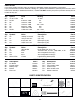
PARTS LIST If you are a student, and any parts are missing or damaged, please see instructor or bookstore. If you purchased this kit from a distributor, catalog, etc., please contact ELENCO® (address/phone/e-mail is at the back of this manual) for additional assistance, if needed. DO NOT contact your place of purchase as they will not be able to help you. RESISTORS Qty.
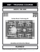
INTRODUCTION Need help in making up your mind? Just ask the SM-200K Decision Maker. Press the ask button and the right answer will be given to your question. The Decision Maker has six light emitting diodes (LEDs) that are driven ON and OFF one at a time in sequence. When the ASK button is pushed the LEDs will flash and the buzzer will sound. After a brief period of time only one LED will remain lit. Above the lit LED is the answer to the question asked.
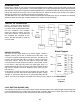
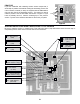
OSCILLATORS The SM-200K uses two oscillators. The first oscillator produces a frequency of about 2000 hertz (cycles per second) and the other produces a frequency of about 20 hertz. Figure 3 shows the basic oscillator circuit.nThe 4011 integrated circuit (IC) contains four-two input NAND gates. Two of these NAND gates are needed to form an oscillator. Feedback for this oscillator is via capacitor C1 and resistors R1 and R2. These elements determine the frequency of oscillation.
CONSTRUCTION Introduction and capacitors. They are very small and are easily lost. Chip resistors are marked with their component value. The first 2 digits are the first 2 digits of the resistance in ohms. The last digit gives the number of zeros following the first 2 digits. The resistor shown at right is therefore 3,900 ohms. The most important factor in assembling your SM-200K Decision Maker Kit is good soldering techniques. Using the proper soldering iron is of prime importance.
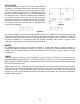
Soldering Tips 2. Apply a small amount of solder to the soldering iron tip. The most important factor in assembling your SM-200K Decision Maker is good soldering techniques. Many areas on the printed circuit board are close together and care must be given not to form solder shorts. Solder shorts may occur if you accidentally touch an adjacent foil, particularly a previously soldered connection, using too much solder, or dragging the iron across adjacent foils.
PRACTICE If you are unfamiliar with soldering surface mount components, it would help to practice a bit before starting the assembly process. Six 0 ohm resistors, marked (0 / 000), are supplied with the SM-200K kit. Only two are used in the assembly process. The other four may be used for practice. Use the PC board area shown in Figure 5. If you have not already done so, read the soldering tips in the previous section. Try both of the methods described to see which you prefer.
SOLDER CAPACITORS AND SEMICONDUCTORS TO PC BOARD D1 - Diode (1N4148) (RA6J), (A6), (A2) or (5H) IC1 - IC (4011) (see Figure 6) C3 - 100µF Lytic (See Figure 8) C4 - 2.2µF Lytic (see Figure 9) + Q1 - Transistor (3904) (R1A), (1A), (N71), (1AM), (KINC), or (ZC) 11 + LED 1 LED 2 LED 3 11 Figure 6 Mount IC with pin 1 as shown on the PC board illustration. IC2 - IC (4017) (see Figure 7) Figure 7 LED 4 LED 5 LED 6 Mount IC with pin 1 as shown on the PC board illustration.
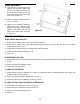
ASSEMBLE LARGE COMPONENTS TO PC BOARD r Place the buzzer on the PC board with the white center facing outward and solder to the PC board at the points shown in Figure 10. Figure 10 Red Black ( ) r Strip 1/8” of insulation off both ends of the short red wire. Solder the wire to the buzzer and the PC board as shown in Figure 10. Be sure the wire is on the center portion of the buzzer and not on the outer rim. r Solder the red and black battery snap wires to the PC board as shown in Figure 10.
FINAL ASSEMBLY r Use scissors or single edge razor blade to cut the thick cushion tape into four 1/4” pieces. Peel off one of the protective layers and stick the tape to the corners of the PC board as shown in Figure 12. r Peel the protective backing off the 3 x 4 1/2” red filter. r Remove the remaining protective backing from the cushion tape. Align the word ASK on the red filter with the 7/32” spacer and stick the filter to the cushion tape as shown in Figure 12.
QUIZ 1) When soldering surface mount resistors, apply the solder... r A) to the component only. r B) simultaneously to the foil and the component. r C) to the foil only. r D) first to the component and then to the soldering iron. 6) The SM-200K uses... r A) 10 oscillator circuits. r B) 6 oscillator circuits. r C) 2 oscillator circuits. r D) none of the above. 2) When driven by clock pulses, the outputs of the decade counter... r A) all go high and remain high.
SCHEMATIC DIAGRAM ELENCO® • 150 Carpenter Avenue • Wheeling, IL 60090 (847) 541-3800 • Fax: (847) 520-0085 • Website: www.elenco.com • e-mail: elenco@elenco.