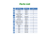
Parts List ID 2 3 5 B1 D1 D2 S1 U15 U16 U17 U18 U19 U20 Part Name 2-snap 3-snap 5-snap Battery holder (dual AA) Mini base grid LED red LED green Jumper wire black Jumper wire red Slide switch Gate Gate Gate Gate Gate Gate Part Number 6SC02 6SC03 6SC05 6SCB1 QTY 2 1 2 1 6SCBGM 6SCD1 6SCD2 6SCJ1 6SCJ2 6SCS1 6SCU15 6SCU16 6SCU17 6SCU18 6SCU19 6SCU20 1 1 2 1 1 1 1 1 1 1 1 1
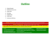
Outline 1. 2. 3. 4. 5. 6. 7. Digital Signals NOT Gate (Inverter) AND Gate OR Gate NAND Gate NOR Gate Exclusive OR Gate Warning: Shock Hazard – Never connect Snap Circuits® to the electrical outlets in your home in any way! Warning: Choking Hazard – Small parts. Not for children under 3 years. Warning: Always check your wiring before turning on a circuit. Never leave a circuit unattended while the batteries are installed. Never connect additional batteries or other power sources to your circuits.
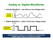
Analog vs.
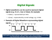
Digital Signals Digital waveforms can be used to represent digital signals (e.g. 0 or 1, true or false), for example • 0 (false) – represented by 0 Volts • 1 (true) – represented by a small voltage, e.g. 3 Volts Example of Digital Waveform representing digital signals True False False True False True True False 1 0 0 1 0 1 1 0 3V 0V Time Digital signals are represented by a “high” state (1) or “true” state consisting of a small voltage (e.g.
Logic Problem Statements Logic problems have outcomes (or outputs) that depend on events (or inputs). For example • The cuckoo clock makes noise if the batteries are not dead AND it’s the top of the hour. • In this example, the output is “the cuckoo clock making noise” and the inputs are “the batteries are not dead” and “it’s the top of the hour”.
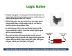
Logic Gates A digital logic gate is an Integrated Circuit (IC) device that makes logical decisions based on various combinations of digital signals presented to it’s inputs. Digital logic gates can have more than one input signal, but generally have a single output signal, just like the decision box on the previous slide. In the following slides, the input digital signals will be represented by A and/or B and the output digital signal will be represented by Q.
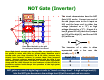
NOT Gate (Inverter) 1 1 2 2 U15 2 1 1 2 2 This circuit demonstrates how the NOT Gate (U15) works. Connect one end of the red jumper wire to the A input on U15 and the loose end to either low voltage (denoted as a “0”) or high voltage (denoted as a “1”). If input A is low (0, green LED off), then the Q output on U15 will be high (1), and the red LED (D1) will be on.
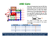
AND Gate This circuit demonstrates how the AND Gate (U16) works. Connect one end of the red and black jumper wires to the A & B inputs on U16 and the loose ends to either low voltage (denoted as a “0”) or high voltage (denoted as a “1”). If, and only if, both input A AND input B are high (both 1s, both gree LEDs on), then the Q output on U16 will be high (1), and the red LED (D1) will be on.
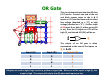
OR Gate This circuit demonstrates how the OR Gate (U17) works. Connect one end of the red and black jumper wires to the A & B inputs on U17 and the loose ends to either low voltage (denoted as a “0”) or high voltage (denoted as a “1”). If either input A OR input B are high (1, either green LED is on), then the Q output on U17 will be high (1), and the red LED (D1) will be on. 1 1 2 2 U17 2 1 1 2 2 A B 2 2 0 1 Q The output of an OR gate is often represented as the sum of the inputs, so Q = A+B.
NAND Gate This circuit demonstrates how the NAND Gate (U18) works. Connect one end of the red and black jumper wires to the A & B inputs on U18 and the loose ends to either low voltage (denoted as a “0”) or high voltage (denoted as a “1”). If either input A OR input B are low (0, either green LED is off), then the Q output on U18 will be high (1), and the red LED (D1) will be on.
NOR Gate This circuit demonstrates how the NOR Gate (U19) works. Connect one end of the red and black jumper wires to the A & B inputs on U19 and the loose ends to either low voltage (denoted as a “0”) or high voltage (denoted as a “1”). If, and only if, both input A AND input B are low (0, both green LEDs are off), then the Q output on U19 will be high (1), and the red LED (D1) will be on.
Exclusive OR (XOR) Gate This circuit demonstrates how the Exclusive OR (XOR) Gate (U20) works. Connect one end of the red and black jumper wires to the A & B inputs on U20 and the loose ends to either low voltage (denoted as a “0”) or high voltage (denoted as a “1”). If input A and input B are exclusive (i.e. different, one green LED is on and the other green LED is off), then the Y output on U20 will be high (1), and the red LED (D1) will be on.
Quiz 1. The output will be LOW (0) for any case when one or more input is LOW (0) for a(n): a) b) c) d) OR gate NAND gate AND gate XOR gate 2. The output of a NOR gate is HIGH (1) if: a) b) c) d) All inputs are HIGH (1) Any input is HIGH (1) Any Input is LOW (0) All inputs are LOW (0) 3.
Quiz Answers 1. The output will be LOW (0) for any case when one or more input is LOW (0) for a(n): a) b) c) d) OR gate NAND gate AND gate XOR gate 2. The output of a NOR gate is HIGH (1) if: a) b) c) d) All inputs are HIGH (1) Any input is HIGH (1) Any Input is LOW (0) All inputs are LOW (0) 3.
ELENCO ® 150 Carpenter Avenue Wheeling, IL 60090 (847) 541-3800 Website: www.elenco.com e-mail: elenco@elenco.