
Installation Instructions


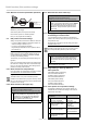

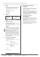

5.3 Connection example, RolTop-915 120 V / 60 Hz
N
PE
L1
sw
br
bl
gr/ge
3
2
1
Fig. 5 Circuit diagram RolTop-915 120 V / 60 Hz and
Wiring when using a Hirschmann plug connection
STAS-3 (with bridge)
5.4 Parallel connection
Important
You can connect several RolTop-915 systems in parallel. To
do so, please observe the maximum control capacity.
5.5 Commissioning
Important
On delivery, the drive system is set to commissioning mode.
►It is necessary to set the end positions with the elero
installation cable (refer to fi g. 6) or a elero wand/hand
transmitter (refer to fi g. 7).
►Connecting the installation cable is only for commissio-
ning of the drive system and for confi guration.
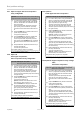
5.5.1 Installation cable connection
blue (neutral) (1)
black (2)
brown (3)
g
reen-yellow
Fig. 6 Installation cable connection
►Switch on power supply.
►Now, you can set the end positions with the elero instal-
lation cable.
1 Winding thermostat
2 Device plug
3 Junction box
(outside of roller shutter case)
4 Electronic
5 Condenser
sw black
br brown
bl blue
gr/ge green/yellow
6 | US+CA © elero GmbH
Installation: Electrical connection
5.2 Electrical connection
WARNING
Danger to life due to incorrect electrical connection.
Risk of electric shock.
►Before initial commissioning, check the correct connec-
tion of the PE conductor.
NOTE
Damage to the RolTop-915 due to incorrect electrical con-
nection.
►Before initial commissioning, check the correct connec-
tion of the PE conductor.
Damage to or destruction of the RolTop-915 due to ingress
of humidity.
►For devices with protection class IP44, the customer-
provided connection of cables or plugs (wiring) must also
be compliant with protection class IP44.
Damage to or destruction of the RolTop-915 for models
with 120 V 1 AC due to incorrect control.
►Switches that are preset to OFF (dead man) for drive
systems must be mounted in viewing range of the Rol-
Top-915 but away from moving parts and at a height
above 1.5 m.
Important
For electrical connection, generally no connection and dis-
connection of the connection cable or plug is necessary.
Particularly at the RolTop915 type S and depending on the
used mounting or adapter plate, it is necessary to remove
this screwed plate before replacing cables.
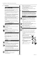
Only connect when the system is disconnected from
the voltage. To do so, disconnect the drive cable.
1 Use a suitable screwdriver to push the locking mecha-
nism of the device plug to the cable.
2 Disconnect the plug.
3 Insert the device plug until the locking mechanism enga-
ges.
Removing and inserting the device plug
Delivery con-
dition
Remove plug Insert plug
Fig. 4 Removing and inserting the device plug
→
1
→
2
→
3