
Installation Instructions


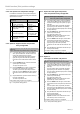


Press one of the drive buttons until the drive system indica-
tes switchover to setting mode with a short automatic stop.
Now, you can set the end positions. After setting both end
positions, the setting mode is closed.
5.6.1 Relief function for end position(s)
If one end position was programmed to limit stop, an additi-
onal relief function can be activated for the fabric.
Important
Activation of the relief function (for options B to D) is carried
out in one step with programming of the end positions (refer
to sections 5.6.7 to 5.6.9)!
5.6.2 Relief function at the upper stop
For option B (refer to section 5.6.7)
and option C (refer to section 5.6.8):
Activating the relief function at the upper limit stop
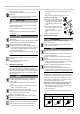
1
Using the installation cable, keep the UP button ▲
pressed from step ① (section 5.6.7 and 5.6.8) and
press additionally (simultaneously) the DOWNbutton
▼. Keep both buttons pressed until the fabric stops.
The relief function at the upper limit stop is activated.
5.6.3 Relief function at the lower stop
For option C (refer to section 5.6.8)
and option D (refer to section 5.6.9):
Activating the relief function at the lower limit stop
1
Using the installation cable, keep the DOWN button
▼ pressed from step ③ (section 5.6.8 and 5.6.9)
and press additionally (simultaneously) the UPbutton
▲.Keep both buttons pressed until the fabric stops.
The relief function at the lower limit stop is activated.
5.6.4 Changing / deleting of end positions
and deleting the relief function
It is not possible to change or delete one individual end
position. This is always carried out in pairs (upper and lower
end position at once).
By deleting the end positions, also the setting of the optio-
nal relief function is lost.
Important
Complete, uninterrupted up and down movement is neces-
sary to adapt the fabric protection system to the fabric.
Changing / deleting of end positions
1
In a medium fabric position, using the installation
cable, simultaneously press both direction buttons (▲
and ▼) and keep them pressed until the drive system
briefl y moves up and down.
Deleting the end position settings is completed.
The end positions can be reset.
6 | US+CA © elero GmbH
Installation: Electrical connection | End position settings
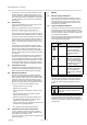
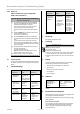
5.3 Connection example, RolTop 120 V / 60 Hz
PE
N
L1
1
0
2
sw
br
bl
gr/ge
1
2
3
4
7
6
5
3
2
1
3
2
1
Fig. 5 Circuit diagram RolTop 120 V / 60 Hz and
Wiring when using a Hirschmann plug connection
STAS-3
Important
The motor controls in up and down direction must be inter-
locked.
5.4 Parallel connection
Important
You can connect several RolTop systems in parallel. To do
so, please observe the maximum control capacity.
5.5 Commissioning
Important
On delivery, the drive system is set to commissioning mode.
►It is necessary to set the end positions with the elero
installation cable.
►Connecting the installation cable is only for commissio-
ning of the drive system and for confi guration.
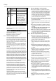
Blau (Neutralleiter) (1)
Schwarz (2)
Braun (3)
Grün-gelb
elero
Blau (Neutralleiter) (1)
Schwarz (2)
Braun (3)
Grün-gelb
Fig. 6 Installation cable connection
►Switch on power supply.
►Now, you can set the end positions with the elero instal-
lation cable.
5.6 End position and relief settings
Important preliminary consideration:
Before carrying out the end position settings, decide on
a certain relief function (different combinations available
according to the following models).
This will save you unnecessary time and effort during con-
fi guration!
1 Winding thermostat
2 Device switch
3 Junction box
4 Switch box
5 Shutter switch /
Shutter button
6 Electronic
7 Condenser
sw black
br brown
bl blue
gr/ge green / yellow