
Installation Instructions


The power connection must be designed according to the
information in the electrical circuit diagram (type and level
of voltage).
One circuit breaker is suffi cient to disconnect the system
from the mains supply (if only one phase and neutral is
used).
If one fi xed (stationary installed) drive system is not
equipped with a mains cable with plug or other means
of disconnection from the mains supply with a contact
opening width according to the provisions of overvoltage
category II (according to IEC 60664-1) for full disconnect,
an isolating device of this kind must be installed into the
fi xed electrical installation according to the installation
regulations.
Mains connection cables for drive systems with rubber
hose cables (code 60245 IEC 53) must always be repla-
ced by cables of the same type.
The following applies for drive systems with access to
unprotected, movable parts after installation: Movable
parts of the drive system must be installed at least 2.5 m
above the ground (or another level providing access to
the drive system).
4 Product description
The SunTop is a electromechanical tubular motor drive.
During operation it carries out radial movements.
Commissioning of the SunTop with elero installation
cable for setting of various functions.
Fabric protection system with retraction
Fabric relief function (fabric protection system)
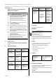
• The values for your SunTop model can be found on the
name plate.
• Depending on torque and size, the different models of
the SunTop are equipped with different types of braking
systems. This may lead to different operating properties
e. g. when approaching end positions.
5 Installation
CAUTION
Risk of injury due to hot surfaces.
The drive system gets hot during operation, therefore the
housing may be hot. Risk of skin burns.
►Wear personal protective equipment (protective gloves).
Due to potential material defects, a broken gear unit, drive
or coupling defect may cause injuries from impacts or
shocks.
►For design of the system, suitable materials were used
and a sampling test in form of a double load test accor-
ding to DIN EN 60335-2-97 was carried out.
Risk of injury from impacts or shocks due to incorrectly
installed or not properly engaged motor bearings. Risk due
to insufficient stability and stored energy (gravity).
►Selection of motor bearings according to torque specifi -
cations.
►The drive system must be secured with all provided
safety equipment.
►Inspection for proper engagement on the motor bearing
and correct screw tightening torques.
4 | US+CA © elero GmbH
Product description | Installation
Without approval by the manufacturer, no modifi cation,
extensions or alterations must be carried out on the
product.
The system must be regularly checked for imbalance or
signs of wear or damaged cables and springs (if appli-
cable).
3.7 Safety instructions on transport,
assembly and installation
In general, the respective transport company is responsible
for transporting the product. The following safety require-
ments must be observed during transport, assembly and
installation of the product:
During transport, the product must be secured according
to the regulations of the used means of transport.
For transport, only hoisting equipment and suspension
gear must be used that are appropriately dimensioned
for safely handling the forces occurring during loading,
unloading and assembly of the product.
Only points defi ned for hoisting or suspension at the
pallet and the product must be used for hoisting or sus-
pension.
If work must be carried out under suspended parts or
working equipment, these must be secured against falling
by suitable means. It must be ensured by suitable hois-
ting equipment that loads drift unintentionally, fall or get
unhooked unsupervised.
Standing under suspended loads is forbidden.
During loading with hoisting equipment, a safety helmet
must be worn.
Assembly and installation must generally only be carried
out by trained and suitably instructed specialists.
The rated torque and the rated operating time must be
suitable for the properties of the driven component („fa-
bric“).
The smallest internal tube diameter for the winding shaft
is 47 mm for SunTop type M and 58 mm for SunTop type
L.
Access to the drive system must be ensured by a freely
accessible appropriately sized inspection fl ap that can
easily be opened.
3.8 Safety instructions on operation
Before initial commissioning, the operator is obliged to
inspect the product for safe and proper operation.
Inspections must also be carried out during operation of
the product in regular intervals defi ned by the operator.
3.9 Safety instructions on electrical installation
Work on the electric system of the used equipment must
only be carried out by authorized electricians according to
applicable rules and regulations by the trade association,
particularly the provisions of DIN VDE 0100. Additionally,
the national legal regulations of the respective country of
operation must be observed.
In case of defects like loose connections or defective or
damaged cables on the system, the product must not put
into operation.
Prior to any inspection, installation or disassembly work,
the system (blinds, shutter) must be disconnected from
the voltage.
All electrical connections, safety equipment, safeguards
etc. must be properly installed, connected and grounded.