
User's Manual


5 Installation
CAUTION
Risk of injury due to hot surfaces.
The drive system gets hot during operation, therefore the
housing may be hot. Risk of skin burns.
►Wear personal protective equipment (protective gloves).
Due to potential material defects, a broken gear unit, drive
or coupling defect may cause injuries from impacts or
shocks.
►For design of the system, suitable materials were used
and a sampling test in form of a double load test accor-
ding to DIN EN 60335-2-97 was carried out.
Risk of injury from impacts or shocks due to incorrectly
installed or not properly engaged motor bearings. Risk due
to insufficient stability and stored energy (gravity).
►Selection of motor bearings according to torque specifi -
cations.
►The drive system must be secured with all provided
safety equipment.
►Inspection for proper engagement on the motor bearing
and correct screw tightening torques.
WARNING
Risk of injury due to electricity.
Risk of electric shock.
►Electrical work must only be carried out by authorized
electricians.
Risk of injury due to electricity.
Potential risk from parts that have become live due to a
malfunction.
►The electrical connection including wiring is described in
the operating and installation instructions.
CAUTION
Risk of injury due to malfunctions due to incorrect installa-
tion.
Excessive winding of the drive system leads to possible
destruction of system parts.
►For safe operation, end positions must be set / program-
med.
►Training courses by the manufacturer for specialized
companies.
NOTE
Power supply failure, braking of machine components and
other defects.
►For safe operation, the system must be properly installed
and the end positions must be set on commissioning.
Damage to the RolTop-915 by humidity ingress.
►On protection class IP44 systems, all cables or plugs
must be protected against ingress of humidity. This ac-
tion must be taken immediately after removing the Rol-
Top-915 from its original packaging.
►The drive system must be installed in a position safe from
rain.
Important
On delivery (factory settings), the RolTop-915 is in commis-
sioning mode.
►It is necessary to set the end positions
(refer to section 5.6).
Optimum use of the wireless signal.
►Position the antenna as freely as possible and reposition
it in case of bad reception.
►Do not bend, shorten or extent the antenna.
►Observe the minimum distance between two wireless
drive systems of 15 cm.
5.1 Mechanical mounting
Important preliminary consideration:
The working space around the installed drive system is
often limited. Therefore, get an overview of the implementa-
tion of the electrical connection (refer to section 5.2) prior to
the mechanical installation and carry out respective chan-
ges, if necessary.
NOTE
Damage to electrical lines by pressure or tensile loads.
►All electrical lines must be laid safe from pressure or
tensile loads.
►Observe the bending radius of the cables (at least 50
mm).
►Lay connection cables in a loop downwards to prevent
water from running into the system.
Damage to the drive system by impact loads.
►Always slide the drive system onto the shaft. Never ham-
mer onto the shaft or the drive system!
►Never drop the drive system!
Damage to or destruction of the drive system by drilling.
►Never drill into the drive system!
Important
Attach the RolTop-915 only to the provided mounting ele-
ments.
Firmly mounted control units must be visible attached.
• The fabric must be mounted on the winding shaft.
• The profi le tube must have suffi cient clearance to the
motor tube.
• Make sure there is suffi cient axial play (1 - 2 mm).
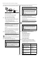
Installation in profi le tubes
Ⓐ Push the drive with suitable adapter
and driving collar into the profile tube.
Protect the motor cable in order to
avoid damage from the driven com-
ponent.
Ⓑ Secure the counterbearings to pre-
vent axial movement, e. g. screw or
rivet on shaft carrier.
Axially secure the drive in the bea-
ring!
Ⓒ Attach the fabric to the shaft!
B
A
C
© elero GmbH US+CA | 5
Installation | Mechanical mounting