
User's Manual Part 2


9
When the apparatus is put within a combined system it is directly connected to the input splitting and output
combining systems.
Before fully powering the apparatus, check that the output connections of the coaxial cable to the antenna
system are working.
In order to this it is possible to check the indication of the reflected power at low power levels. Only if the
SWR indication on the display is 0, the output power can be slowly increased. At maximum output power,
some watts might be shown as reflected power.
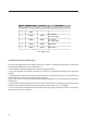
2.3 TELEMEASURING SOCKET CONNECTIONS
DB9 Socket
2.4 RS232, RS485 AND AGC SOCKET CONNECTIONS
PIN N° SIGNAL TYPE IN / OUT FUNCTION
1Analog OutputFWD Power
2 Analog Output REF Power
3 Digital Output Temperature
4 Digital Input Interlock
5 GND - -
6 - 7 Digital Output Free contact (closed when alarm)
8 Digital Input
0V = ON
5V = Normal
9 Digital Input
0V = OFF
5V = Normal
PIN
123456789
FUNCTIONS
-TxDRxD-GND- - - -
RS232 - DB9 Socket
PIN
123456789
FUNCTIONS
-Rx-Rx+5VGND-Tx-Tx+-
RS485 - DB9 Socket