VEGA UHF - TV System Users manual CODE: APT139NM2 TITLE: VEGA REV: 0 DATE: 15/02/05
Registration number: IT-17686 Registration number: IT-24436 SS 96 Km 113 70027 Palo del Colle (Ba) ITALY Tel. +39 (0)80 626755 Fax +39 (0)80 629262 E-mail: elettronika@elettronika.it Web site: http://www.elettronika.
Index Index ................................................................................................................................... 3 Warning .............................................................................................................................. 5 Warranty ............................................................................................................................. 6 Introduction ..............................................................................
Cable diagram ............................................................................................................... 58 APT139NM2 VEGA - Component list ............................................................................... 59 MTG0071AR1 (Multistandard Audio Mono Modulator Module) .................................... 60 MTG0078AR0 (Multistandard Audio Stereo Modulator Module) ................................... 67 MTG0072AR0 (Multistandard Video Modulator Module) ...........................
WARNING The apparatus described in this manual has been designed and manufactured with devices to safeguard the users. In any case it is recommended that during any operation of installation, maintenance, miscellaneous interventions and calibrations requiring the apparatus to be switched on, THE USER TAKES ALL THE PRECAUTIONS AGAINST INCIDENTS It is required to use the proper clothes and protection gloves in order to prevent damages from incidental contacts with high-voltage parts.
Warranty Summary of warranty We, ELETTRONIKA S.r.l., SS096 Km 113 Z.I. PALO DEL COLLE (BA) ITALY, warrant to the ORIGINAL PURCHASER of a NEW product, for a period of one (1) year from the date of purchase by the original purchaser (the warranty period) that the new ELETTRONIKA product is free of defects in materials and workmanship and will meet or exceed all advertised specifications for such a product.
INTRODUCTION The apparatus described in this manual is the latest of this series, offering high performances, remarkable reliability and a wide range of characteristics, it all at a low cost. Its is easy to install and use. It only takes to follow the installation procedure as shown in this manual: after having removed all from the package, you only have to follow step by step the description in the various sections.
WARNING! The currents and voltages in this equipment are dangerous! Personnel must at all times observe safety regulation! This manual is intended as a general guide for trained and qualified personnel who are aware of the dangers inherent in handling potentially hazaedous electrical and electronic circuits. It is not intended to contain a complete statement of all safety precautions which should be observed by personnel in using this or other electronic equipment.
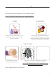
Treatment of electrical shock 1) If victim is not responsive follow the A, B, Cs of basic life support. PLACE VICTIM FLAT ON HIS BACK ON A HARD SURFACE A - AIRWAY B - BREATHING If unconscious, open airway lift up neck, push forehead back, clear out mouth if necessary, observe for breathing. If not breathing, begin artificial breathing. Tilt head, pinch nostrils, make airttght seal, 4 quick full breaths. Remember mouth to mouth resuscitation must be commenced as soon as possible.
2) If victim is responsive: - keep them warm; - keep them as quiet as possible; - loosen their clothing (a reclining position is recommended). FIRST-AID Personnel engaged in the installation, operation, maintenance or servicing of this equipment are urged to become familiar with first-aid theory and practices. The following information is not intended to be a complete first-aid procedure, it is brief and is only to be used as a reference.
UHF - TV SYSTEM VEGA Users manual 11
This page is intentionally blank 12
_______________________________________________________________________________________________ Section 1 - Information Contents: 1.1 Description 1.2 Main features 1.
VEGA UHF - TV SYSTEM 1.1 DESCRIPTION The transmitters and transposers in this series VEGA are characterized by high performance and capability and by excellent linearity over the entire band thanks to the optimization of the RF circuits. A high degree of reliability is guaranteed, moreover, by the use of oversized cooling devices and by control circuits operated by modern microprocessor technologies.
1.3 TECHNICAL CHARACTERISTICS VIDEO PARAMETERS AUDIO PARAMETERS GENERAL Input impedance Input level White / Sync level limiter 2T K factor Amplitude / frequency response Differential gain Differential phase Group delay Sync pulse compression S/N ratio (weighted) Pre-emphasis ICPM Luminance non linearity Field time bar tilt Line time bar tilt 75W 1Vpp ±6dB 95% < 1.5% ±0.
Front panel 1 2 3 4 5 6 DESCRIPTION 16 1 Mult. Mono Audio Modulator Module 2 Mult. Video Modulator Module 3 Mult. IF Precorrector Module 4 Mult. UHF Local Oscillator Module 5 Mult.
Rear panel 5MHz IN/OUT DESCRIPTION 3 2 Power Supply Module 3 External Referement Module 2 RF RF 1 TELEMEASURES AUDIO2 IF LINK RS485 VIDEO RF Amplifier Module RF 1 17
This page is intentionally blank 18
_______________________________________________________________________________________________ Section 2 - Operation Contents: 2.1 Menu Management 2.2 Manu Description 2.
2.1 MENU MANAGEMENT A large number of options of the VEGA TV exciter can be easily and intuitively controlled through the humanto-machine interface on the right side of the VEGA. It is composed by a graphic display and a clickable knob. When the VEGA is switched on it initialise itself and query to all attached boards on bus the release number. During this period the display shows the screen below.
All of the menus of the VEGA contain a top bar which shows the name of the apparatus, the firmware version of the display board and the current time, and a bottom bar showing the reading of the output forward and reflected power and a summary of the current menu. Since the number of menus of the VEGA is high, we give hereby a detailed description of all menus. Note that the same firmware works either with the mono audio modulator and the stereo one.
settings; - the parameters which can be continuously set are represented by a bar showing the indication of the current value (light) and of the one set at the factory (dark); - Actions (e.g. "Clear History") are always followed by the ->|<- symbol. By selecting this voice and cofnirming, the action will be executed. l Pressing the knob while in any of the menus turns on a blinking cursor which can be used to select any parameter simply by turning the control.
Limiter Clicking on then knob, after selecting this voice, goes into the menu that allows to change the Enables or Disables the limitation circuit. Rotate the knob to select the desired value and click on it. Answer to the confirming question, selecting between accept or not. The answer starts always from "Accept: NO", so to exit quickly form this menu simply click 2 times on the knob.
SC Shows the PLL lock or unlock of the subcarrier. In case of unlock, the label blinks. SCDev Shows the Deviation in kHz of the subcarrier. AudioLvl Clicking on then knob, after selecting this voice, goes into the menu that allows to sets the input audio signals level. Rotate the knob to select the desired value and click on it. Answer to the confirming question, selecting between accept or not. The answer starts always from "Accept: NO", so to exit quickly form this menu simply click 2 times on the knob.
- Multistandard Audio Stereo Section (Option) The last menu is showed as in stereo or mono mode settings. If the mode is set for a dual sound audio modulation the last menu become the one below, because you can select to adjust the audio level to different values. EXIT Clicking on the knob, after selecting this voice, goes back to the default menu. OverloadL and OveroadR Shows whether there is (Prst), there isn't (Abst) or there was (Trig) an overload of the audio left and right signal.
Limiter Clicking on then knob, after selecting this voice, goes into the menu that allows to change the Enables or Disables the limitation circuit. Rotate the knob to select the desired value and click on it. Answer to the confirming question, selecting between accept or not. The answer starts always from "Accept: NO", so to exit quickly form this menu simply click 2 times on the knob.
Mode Clicking on then knob, after selecting this voice, goes into the menu that allows to choose the operating mode between mono, stereo or dual sound. Rotate the knob to select the desired value and click on it. Answer to the confirming question, selecting between accept or not. The answer starts always from "Accept: NO", so to exit quickly form this menu simply click 2 times on the knob. Emph.
Answer to the confirming question, selecting between accept or not. The answer starts always from "Accept: NO", so to exit quickly form this menu simply click 2 times on the knob. IF2 Level Clicking on then knob, after selecting this voice, goes into the menu that allows to sets the IF2 level. Rotate the knob to select the desired value and click on it. The actual level is represented by the empty arrow, the full arrow represent the value of the factory setting of this level.
- Multistandard Video Section EXIT Clicking on the knob, after selecting this voice, goes back to the default menu. White Clip Shows whether there is (Prst), there isn't (Abst) or there was (Trig) the clipper intervention on white. In Absent and Triggered case, the label blinks. Sync Clip Shows whether there is (Prst), there isn't (Abst) or there was (Trig) the clipper intervention on sync. In Absent and Triggered case, the label blinks.
Sync Restore Clicking on then knob, after selecting this voice, goes into the menu that allows to toggle the sync restore intervention. Rotate the knob to select the desired value and click on it. Answer to the confirming question, selecting between accept or not. The answer starts always from "Accept: NO", so to exit quickly form this menu simply click 2 times on the knob.
- Multistandard IF Precorrector Section EXIT Clicking on the knob, after selecting this voice, goes back to the default menu. Prec Clicking on then knob, after selecting this voice, goes into the menu that allows to toggle the non-linearity pre-corrector. Rotate the knob to select the desired value and click on it. Answer to the confirming question, selecting between accept or not. The answer starts always from "Accept: NO", so to exit quickly form this menu simply click 2 times on the knob.
- Multistandard Local Oscillator Section with Line Offset EXIT Clicking on the knob, after selecting this voice, goes back to the default menu. Channel Clicking on then knob, after selecting this voice, goes into the menu that allows to select the transmission channel for the selected standard. Rotate the knob to select the desired value and click on it. Answer to the confirming question, selecting between accept or not.
Output Clicking on then knob, after selecting this voice, goes into the menu that allows to toggle the oscillator output. Rotate the knob to select the desired value and click on it. Answer to the confirming question, selecting between accept or not. The answer starts always from "Accept: NO", so to exit quickly form this menu simply click 2 times on the knob. Ref Clicking on then knob, after selecting this voice, goes into the menu that allows to select whether the reference is internal or external .
- Multistandard Local Oscillator Section with Field Offset (Option) EXIT Clicking on the knob, after selecting this voice, goes back to the default menu. Channel Clicking on then knob, after selecting this voice, goes into the menu that allows to select the transmission channel for the selected standard. Rotate the knob to select the desired value and click on it. Answer to the confirming question, selecting between accept or not.
Answer to the confirming question, selecting between accept or not. The answer starts always from "Accept: NO", so to exit quickly form this menu simply click 2 times on the knob. DRO, VCO, STD Shows the oscillator PLLs lock or unlock. In case of unlock, the label blinks. Output Clicking on then knob, after selecting this voice, goes into the menu that allows to toggle the oscillator output. Rotate the knob to select the desired value and click on it.
- Multistandard Channel Filter Section EXIT Clicking on the knob, after selecting this voice, goes back to the default menu. PwrCtrlMode Clicking on then knob, after selecting this voice, goes into the menu that allows to switch between the manual and automatic (AGC) power control mode. Rotate the knob to select the desired value and click on it. The Auto or Manual selection will be always displayed on the top bar. ATTENTION: for safety operation is better to set 0% to the power level that in not selected.
Answer to the confirming question, selecting between accept or not. The answer starts always from "Accept: NO", so to exit quickly form this menu simply click 2 times on the knob. SqlchTime Clicking on then knob, after selecting this voice, goes into the menu that allows to choose the squelch time. This is the time without input signal after which the VEGA mute the power amplifier.
ExtAgcStat Shows the External AGC working status. It can be: · Disabled: AGC disabled by local or remote menu setting. · Idle: AGC temporary stopped (for example caused by -3dB power reduction without sync). · Low Set: AGC stopped because external power reading too low when VEGA power has been choosed. · Alarm: AGC stopped because Alarm signal set by Amplifier section. · Lock: AGC has reached the desired power. · Max/Min: AGC stopped because the correction is too hi.
- Controller Module Section EXIT Clicking on the knob, after selecting this voice, goes back to the default menu. Hist View Clicking on then knob, after selecting this voice, goes into the menu that allows to show all the events stored into the non volatile memory of the VEGA. In the title bar is showed the current event number and the total events actually stored into the log. To move inside the log simply rotate the knob. Click the knob to exit from the history view.
Answer to the confirming question, selecting between accept or not. The answer starts always from "Accept: NO", so to exit quickly form this menu simply click 2 times on the knob. Brightness Clicking on then knob, after selecting this voice, goes into the menu that allows to adjust the brightness settings of the display. Rotate the knob to select the desired value and click on it. Answer to the confirming question, selecting between accept or not.
Answer to the confirming question, selecting between accept or not. The answer starts always from "Accept: NO", so to exit quickly form this menu simply click 2 times on the knob. Time Clicking on then knob, after selecting this voice, goes into the menu that allows to set the time of the internal clock of the display board. Rotate the knob to select the desired value and click on it, the selection will go to the next filed. The time format is hour/minute/second.
TLMout Clicking on then knob, after selecting this voice, goes into the menu that allows to toggles between Squelch or Alarm meaning of the output free contact of the Telemeasure connector. Rotate the knob to select the desired value and click on it. Answer to the confirming question, selecting between accept or not. The answer starts always from "Accept: NO", so to exit quickly form this menu simply click 2 times on the knob.
- RF Amplifier Module Section EXIT Clicking on the knob, after selecting this voice, goes back to the default menu. LockOut Shows whether the LockOut state is present or absent. In case of presence of LockOut, the label blinks. Below is detailed the functioning of LockOut. While an alarm is present the exciter switch off the output power. When the alarm disappear, the power is switched on again.
automatically depending on the temperature of the final stage. The fan symbol on the right shows the fan speed: 0, 1 or 2 means respectively stopped, low and high speed. Clicking on then knob, after selecting this voice, goes into the menu that allows to set the standard used. Rotate the knob to select the desired value and click on it. Answer to the confirming question, selecting between accept or not.
- BUS Structure Section EXIT Clicking on the knob, after selecting this voice, goes back to the default menu. Power Clicking on then knob, after selecting this voice, goes into the menu that allows to turns on or off the power supply of the whole BUS. Rotate the knob to select the desired value and click on it. Answer to the confirming question, selecting between accept or not. The answer starts always from "Accept: NO", so to exit quickly form this menu simply click 2 times on the knob.
- External Reference Section EXIT Clicking on the knob, after selecting this voice, goes back to the default menu. IF link Clicking on then knob, after selecting this voice, goes into the menu that allows to choose whether the IF connection is internal or located on the rear panel. Rotate the knob to select the desired value and click on it. Answer to the confirming question, selecting between accept or not.
a good value, without ant instrumentation. Answer to the confirming question, selecting between accept or not. The answer starts always from "Accept: NO", so to exit quickly form this menu simply click 2 times on the knob.
2.3 ALARMS AND AUTOMATION In case of alarm the red LED lights up and the icon of a bell appears in the upper bar of the display. If the alarm disappears, the red LED is turned off and the bell starts blinking, in order to show that an anomaly occurred. To know the details of the anomaly and when it occurred, the history menu can be used. Once this menu is accessed, the blinking bell icon disappears.
If the temperature drops again below TH3, the amplifier is switched back on. A fast sequence of on/off switching causes a LockOut of the apparatus. l BUS Voltages (+5V, +15V, -15V) No intervention. The history records and intervention if the value is too high or too low by the 10% of its nominal value. l Forward & Reflected Power If the value of the forward power exceeds the threshold value (factory setting) the ampifier is switched off and the event is recorded in the alarm history.
Besides, the final amplifier is switched off. l No Sync In case the synchronism is missing the sync icon in the top bar blinks. In this case the value of the output power is decreased by 3dB only if analog signal type is selected and AGC control is selected. In case of 3dB otput power decrease, the output power value in the bottom bar will be written between round brackets. l Squelch After a selectable time the video input signal is missing the VEGA mute the output power.
AGC implementation The AGC goal is to maintain stable the output power. Output power in fact can change due to the increase of amplifier temperature. Note that when you change the operating frequency the output power change due to the different gain at different frequency, but this change is not stabilized by this AGC algorithm. The power to stabilize is read from external telemerasuring connector. To keep the power stable the AGC change the power gain of VEGA.
2.5 POWER HANDLING The VEGA Power handling is characterised by 3 state: · BUS OFF: the boards on the Bus are off and the power amplifier is switched off · MUTE: the board on the Bus are switched on and working. Only the power amplifier is switched off. · POWER ON: the boards and the power amplifier are switched on and working. This is the normal working functioning. Moving between the 3 states is always possible by using the display menu or by remote connection.
2.6 VEGA FACTORY SETTING The VEGA display board stores some settings and fine tunings inside its not erasable memory. The storing occurs while the VEGA is tested in factory before the sell. To enter in Factory Setting mode a dip-switch is used. DIP2 On (VEGA display board): Factory setting. Note that DIP2 is set to ON only during the factory setup of the exciter. This allow to store in the memory all of the settings made as factory defaults.
Nominal Voltage Clicking on then knob, after selecting this voice, goes into the menu that allows to change the value of the nominal voltage of the power supply of the power amplifier. Rotate the knob to select the desired value and click on it. Nominal Current Clicking on then knob, after selecting this voice, goes into the menu that allows to change the value of the nominal current of the power supply of the power amplifier. Rotate the knob to select the desired value and click on it.
Then the user have to choose which kind of boards are connected on the bus, moving between front and read view. The modifiable boards are that with symbol under them. Once entered the configuration the user has to go in the rightmost windows and choose the Confirm to change the actual configuration.