
User's Manual Part 3


104
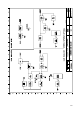
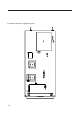
The module contains the following blocks:
1. Local oscillator generated the carrier to be synthesised, it is split into three windows (I-II / III / IV-V
band) to ensure the coverage of all of the TV channels to be implemented for all standards.
2. Radio-frequency splitter splits the signal coming from the local oscillator by means of splitters and
amplifiers, with 10dB attenuation and gain respectively, to ensure the complete isolation of the LO from
the other stages and to minimise the frequency pulling phenomenon.
3. PLL stage synthesises the desired channel by locking the LO to a 20MHz frequency reference by
means of a PLL which can be configured via uWire and provides the locking and line-offset indication
(LED on frontal panel); the choice is made via software.
4. Active ring filter stabilises the system in PLL retro-action and e has to be modified if the operating
band of the module changes (see table attached to the electrical diagram).
5. Conditioning stage of the correction voltage conditions the correction voltage of the PLL ring
providing a conditioned analog voltage for the A/D conversion; the voltage is processed by the
microcontroller of the display board (see MTG0079) to be displayed as VU-METER.
6. Mixer in the UPCONVERTER version of the module, converts to channel the intermediate frequency
coming from the pre-corrector (see MTG0073) using a LEVEL13 mixer (in case the module is only used
as LO, see REPEATER configuration, this stage is not present and the synthesised carrier goes directly to
the output of the module).
7. 20MHz reference the frequency reference to the PLL synthesis of the carrier is generated by an
internal TCXO which fine control of the frequency is internally generated via PWM by the microcontroller
or, alternately, can be locked to a more precise 5/10MHz external reference (see MTG0076).
8. Controller all of the described operations are managed by a microcontroller communicating to the user
interface board (see MTG0079) by RS485 protocol; the local controller stores the status of the module
and a reprogramming of the firmware (possible via RS485 from the display board) does not alter its
contents.
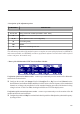
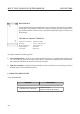
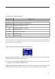
CALIBRATION PROCEDURE
- List of instrument
MEASURE INSTRUMENT
Lock of the carriers and reference
- Spectrum analyser
- Oscilloscope
- Tester