
User's Manual Part 3


105
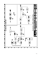
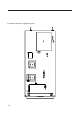
The calibration procedure of the module requires a complete structure of display board (see MTG0079)
and extension module (see MTG0095) in order to perform the software selection which will be referred
to later and power the module itself..
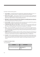
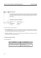
- Menu of the Multistandard UHF Local Oscillator Module
Verification of the local oscillator section connect a spectrum analyser to the monitor of the J4 module
and check the sections therein:
q Configure the module with Output Enabled, LineOffset Zero, Ref Internal and Channel on the
desired channel, and calibrate C1(C2 and C3) to lock the carrier to the LO frequency of the standard and
channel set (to change the standard refer to the standard changing procedure) and obtain a locking
voltage between 2V and 3V on TP1, checking that VCO is on Lock in the display menu.
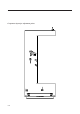
Verification of the external reference section connect a spectrum analyser to the monitor of the J4
module and check the sections therein:
q Configure the module with Ref Internal and check that it is possible to find adjust the synthesised frequency
by acting on Tune.
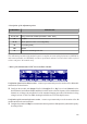
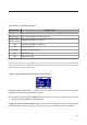
- Description of the adjustment points
COMPONENT DESCRIPTION
C1, C2, C3
Tuning of the local oscillator (SCH0292 - 0309 - 0310)
J3
LO input
J5, J8
RF link (absent in case of LO configuration)
J4
LO monitor (panel)
JP1
Unused
J2
Testpoint for the debug of the PLL