
User's Manual Part 3


109
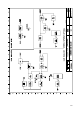
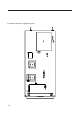
The calibration procedure of the module requires a complete structure of display board (see MTG0079)
and extension module (see MTG0095) in order to perform the software selection which will be referred
to later and power the module itself.
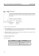
- Menu of the Multistandard UHF Channel Filter Module
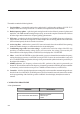
Verification of the channel filter connect a network analyser to the channel filter and calibrate its
components to obtain the desired frequency response:
q Configure the module with PwrCtrlMode Man and verify that it is possible to change the gain of the filter
by acting on PwrLevelMan, setting JP1 Remote.
Verification of the wide-band amplifier section connect a spectrum analyser with tracking between J4
and J5 check that the frequency response of the amplifier is flat within 1dB from 50MHz to 900MHz.
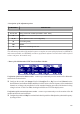
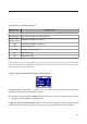
- Description of the adjustment points
COMPONENT DESCRIPTION
C1-C8, C18-19
Channel filter calibration for bands III and IV-V
C17, C20-24,
C26-27, C31-32
Channel filter calibration for band I-II
L1-6
Channel filter calibration for band I-II
J6
RF monitor (panel)
JP1, R29
Local gain control of the filter
J2
Channel filter input
J4
Channel filter output