
User's Manual Part 2


63
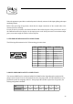
around 32V. Then take the calibration load and connect it between the positive power supply terminal
(corresponding to V1) and ground. Turn the trimmer R5 until you read on the display V1 equal to the value
measured before with the tester. Then turn the trimmer R33 until you read on the display Idr1 = 3.4A.
Repeat the procedure above for the power supplies of the remaining three power transistors: measure with
the tester the voltages V2-V3-V4 and turn the trimmers R7-R9-R11 until you read on the display the correct
values measured.
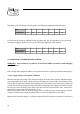
To calibrate the remaining currents readings, you have to connect the calibration load to the other three power
supplies (not all together, but one at a time!) and then turn the trimmers R39-R45-R51 until you read on the
display I2=I3=I4= 3.4A.
- Temperature calibration
Measure with a tester the voltage of the OUT pin of the integrated temperature sensor mounted on the heat
dissipating element. Than perform the operation explained in this example:
- voltage measured (for example) = 2.93V
- fixed number = 2.73
- perform subtraction: 2.93-2.73 = 0.20
If you get a result of 0.20, it means that the temperature is 20°C, so you have to turn the trimmer R102 until
you read TEMP = 20°C.
- Forward power calibration
Disconnect the antenna and connect a wattmeter (with a suitable dummy load!) to the antenna connector. Put
the cover on the amplifier module and then give power to the equipment until you read 1000W on the
wattmeter. Then turn the trimmer R96 until you read FWD = 1000W (approximately).
- Reflected power calibration
To perform the reflected power calibration just disconnect the REF SMB (J6) and the FWD SMB (J7)
connectors from the control board and connect the forward power reading cable to J6 (REF). Give 50W of
forward power to the equipment and turn the R97 trimmer until you read on the display REF = 50W.
Note: When you have completed this calibration be sure to restore the original connections on the
control board!