
User's Manual Part 3


108
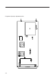
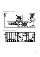
MULT. UHF CHANNEL FILTER MODULE MTG0075AR0
DESCRIPTION
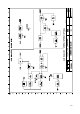
The module filters the signal coming from the conversion mixer removing the local oscillator
and the upper side-band and contains the voltage-controlled gain stage composed by a
pin-diode attenuation cell followed by a wide-band amplification stage used as driver of
the final stage.
TECHNICAL CHARACTERISTICS
Input/output impedance 50W R.O.S.>20dB
Filter type Active 5-cell band-pass
RF-attenuation type 4 PIN-diodes cell
Output amplifier Wide band
Overall gain 25dB (max.)
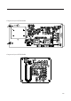
The module contains the following blocks:
1. Active band-pass filter filters the lower side-band after conversion, it is split into three windows (I-II
/ III / IV-V band) to ensure the coverage of all of the TV channels to be implemented for all standards,
and contains the PIN-diode attenuation cell for the gain control.
2. Wide-band amplifier amplifies the filtered channel in order to obtain the correct driving level for the
RF final stages (see MTF0088-0087-0089).
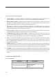
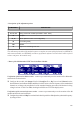
CALIBRATION PROCEDURE
- List of instruments
MEASURE INSTRUMENT
Calibration of the channel filter
- Network analyser
- Spectrum analyser with tracking