
Service manual


1-1
SECTION 1 – THEORY OF OPERATION
1.1 INTRODUCTION
This service manual is intended to assist in the maintenance, troubleshooting, repair
to the module level, and calibration of the Elgar TrueWave (TW) products. The topics
discussed in this manual may require a level of understanding of analog and digital
circuit theory somewhat higher than that required for normal Operator/Programmer
activities. For this reason, only qualified personnel should attempt to troubleshoot and
repair TrueWave products.
This section describes the TW Power Sources and associated circuit boards,
assemblies and interconnecting signals. Topics of this section provide a basis for
understanding the roles performed by the system electronics and should be a precursor
to any troubleshooting or maintenance.
Prior to the module level discussion of the assemblies and boards within the TW
system, a top-level system overview is provided. An understanding of both top level and
circuit activities at the module or board level is most valuable should the service person
find it necessary to investigate a suspected fault or malfunction within the power source.
1.2 SYSTEM OVERVIEW
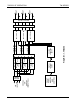
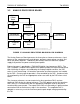
Figure 1-1 shows a simplified block diagram of the TW system. The 3 phase input
voltage is delivered via the input filter to the power module(s) where it is rectified
providing bus voltages for the amplifier(s). Voltage and waveform control signals are
delivered to the amplifier(s) from the front panel assembly. The front panel assembly
contains the Digital Control Board, and the Analog Processor Board (see sections 1.4
and 1.5). From the bus voltages and control signals, the amplifiers then produce output
waveforms, which are delivered via the output filter to the output terminals.
There are three primary options that are available when ordering a TW system, which
with all permutations considered, translates into many different configurations of TW
systems. The options are: PFC or rectifier input, 208VAC or 400VAC input voltage,
power rating of the unit (number of phases installed).
The PFC/rectifier and input voltage options will be discussed in more detail later in this
manual.