
Service manual


SERVICE MANUAL THEORY OF OPERATION
1-3
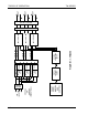
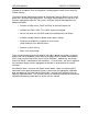
The system shown in Figure 1-1 is a TW5250 meaning that it contains three identical
output channels A, B, and C, with a channel consisting of a power module and an
amplifier module. Each channel is capable of delivering 1750 VA to the output. One and
two channel systems, TW1750 and TW3500, can be achieved by removing channels B
and C, or C only (Note: adding or removing a channel requires reprogramming of the
system). TW10500, TW15750, and TW21000 systems can be produced by adding
additional TW chassis.
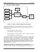
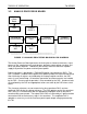
1.3 INTERCONNECTION
The 3 phase input voltage is delivered via the fuse block and input filter to the power
module(s), through W1, 2 and 3, where it is rectified via the PFC or rectifier input
stage(s). The rectified voltages are then delivered to the DC/DC converter(s) where
290V buses are produced and delivered via the backplane board to the amplifier(s). A
48V bus is also produced by the DC/DC converter(s) and delivered via the backplane to
the HSKP board (see section 1.6). The amplifier(s) receive waveform drive signals and
power supply voltages via ribbon cables and a signal routing board. The Digital Control
Board receives external input locally from the front panel keypad or remotely from the
RS232 or GPIB (IEEE 488.2). The Digital Control Board then sends data and
commands to the Analog Processor Board with the desired waveform information to
drive the amplifiers as mentioned above.