Revision B July 2011 Copyright 2011 by AMETEK Programmable Power. All rights reserved.
User Manual California Instruments User's Manual California Instruments AC Power Source By AMETEK Programmable Power. Models : CSW5550 CSW5550-400 CSW11100 CSW11100-400 CSW16650 CSW16650-400 CSW22200 CSW22200-400 CSW27750 CSW27750-400 CSW33300 CSW33300-400 CSW38850 CSW38850-400 CSW44400 CSW44400-400 Copyright 2011 AMETEK Programmable Power. Rev A, March 2011.
User Manual California Instruments About AMETEK AMETEK Programmable Power, Inc., a Division of AMETEK, Inc., is a global leader in the design and manufacture of precision, programmable power supplies for R&D, test and measurement, process control, power bus simulation and power conditioning applications across diverse industrial segments.
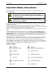
User Manual California Instruments Important Safety Instructions Before applying power to the system, verify that your product is configured properly for your particular application. WARNING Hazardous voltages may be present when covers are removed. Qualified personnel must use extreme caution when servicing this equipment. Circuit boards, test points, and output voltages also may be floating above (below) chassis ground. The equipment used contains ESD sensitive parts.
User Manual California Instruments CSW Series 5
User Manual California Instruments Product Family: CSW Series Power Source Warranty Period: 1 Year WARRANTY TERMS AMETEK Programmable Power, Inc.
User Manual California Instruments Table of Contents 1. Introduction ................................................................................................................................ 12 1.1 General Description ............................................................................................................................. 12 1.2 CSW Models ........................................................................................................................................
User Manual 8. California Instruments Top Assembly Replaceable Parts .......................................................................................... 119 8.1 Sub assemblies ................................................................................................................................. 119 9. Options ..................................................................................................................................... 120 9.1 9.2 9.3 9.4 9.5 9.6 9.7 9.8 9.
User Manual California Instruments List of Figures Figure 1-1 California Instruments CSW5550 (With Rack Mount Ears) ................................................................ 12 Figure 2-1: CSW5550 - Voltage Current rating .................................................................................................... 17 Figure 3-1:CSW5550 ...........................................................................................................................................
User Manual California Instruments Figure 9-7: Power Interrupt for Group 2 and 3 .................................................................................................. 128 Figure 9-8: Emergency Screen ......................................................................................................................... 129 Figure 9-9: Abnormal Screen ............................................................................................................................
User Manual California Instruments List of Tables Table 3-1: Wire Sizes ......................................................................................................................................... 30 Table 3-2: System Interface Connector (J32) ..................................................................................................... 31 Table 3-3: RS232 Connector pin out .................................................................................................................
User Manual California Instruments 1. Introduction This instruction manual contains information on the installation, operation, calibration and maintenance of all power systems that use the CSW5550. This user manual also covers higher power configurations consisting of multiple units of the CSW5550 operated in parallel. Such models are the CSW11100, CSW16650, CSW22200, CSW27750, CSW33300, CSW38850 and CSW44400. Figure 1-1 California Instruments CSW5550 (With Rack Mount Ears) 1.
User Manual California Instruments 1.
User Manual California Instruments 2. Specifications All specifications are for a single CSW5550 unit and 25 5C sine wave output with a resistive load unless noted otherwise. 2.1 Electrical 2.1.1 Input Function Input Power Input Power Factor Specification Standard: 208 to 240VL-L ±10%, 3, 3 wire or option: 380 to 415VL-L ±10%, 3, 4 wire 0.
User Manual California Instruments 2.1.
User Manual Function External Gain Control, RPV California Instruments Specification 0 to +7.07 VDC for 0 to programmed output. 0 to full-scale output for CSW. (±2% of full scale output External Input Impedance 40K for each of the three inputs. XLOAD The CSW5550 is guaranteed to be stable for power factors from 0 leading to 0 lagging. The most difficult load for most amplifiers is driving large capacitive loads (10-10,000F).
User Manual California Instruments Figure 2-1: CSW5550 - Voltage Current rating CSW Series 17
User Manual California Instruments Output Parameter CSW5550 (multiply current and power by the number of power sources in multi-source power systems) Current Limit Range Resolution Accuracy Frequency Range: (Without Cloc/ Lock option enabled) Frequency Accuracy: DC Offset Voltage: 18 Programmable 0 to 100% of range for all ranges 0.01 Arms ± 1% of Range. Add ±1.5%/kHz above 500 Hz 16.00 - 81.91 Hz (0.01 Hz resolution) 81.0 – 819.1 Hz (0.1 Hz resolution) 820 – 5000 Hz (1 Hz resolution) 0.
User Manual California Instruments 2.1.3 Measurements (All specifications are at 25˚C unless noted otherwise) Parameter Accuracy () Resolution Frequency 2 counts 0 to 45˚C 0.01: 16 to 81.91 Hz 0.1: 82.0 to 819.0 Hz 1: 820 to 5000 Hz RMS Voltage ±0.1% of range from 5 to 156 or 10 to 312 volts. Above 1kHz add 0.2%/kHz 0.01 Volt RMS Current ±1% of range add ±1.5%/kHz above 500 Hz Ranges: 0.5 to 16A: 156V range 0.5 to 8A: 312V range Multiply by 3 for 1-phase mode 0.
User Manual California Instruments 2.1.4 Harmonic Measurements (CSW series) Parameter Range Accuracy ( ) Resolution Frequency fundamental 16.00 - 1000 Hz 2 counts 0.01 Hz to 1 Hz Frequency harmonics 32.00 Hz - 16 kHz 2 typ. 0.5 Voltage Fundamental 0.25V 0.01V Harmonic 2 - 50 0.25V + 0.1% + 0.1%/kHz 0.01V Fundamental !% of Range 0.01A Harmonic 2 - 50 1% of Range + 0.1%/kHz 0.01A Current Harmonics frequency range in three-phase mode is 32 Hz - 16 kHz.
User Manual California Instruments 2.1.5 System Specification Parameter Specification NV memory storage: 16 complete instrument setups and transient lists, 100 events per list. Waveforms Sine, square, clipped, user defined Transients Voltage: drop, step, sag, surge, sweep Frequency: step, sag, surge, sweep Voltage and Frequency: step, sweep IEEE-488 Interface: SH1, AH1, T6, L3, SR1, RL2, DC1, DT1 IEEE 488.
User Manual Parameter California Instruments System Specification (continued) Specification Front Panel Trigger, BNC connector Output available at the front panel BNC connector that provides a negative going pulse for any programmed voltage or frequency change. The trigger can be reassigned as an output when running list transients. Front Panel Phase A, B and C, BNC connectors These three outputs are representative of the programmed output waveform, magnitude and frequency. 0 to 4.
User Manual California Instruments 2.2 Mechanical Parameter Specification Dimensions: 19” (483 mm) wide x 8.75” (222 mm) high x 23.5” (597 mm) deep chassis size which is available in a rack mount or stand-alone configuration. Unit Weight: 126.5 lb. (57.2 kg) Material: Steel chassis and front panel, Aluminum top cover and rear panel. Finish: Light textured painted external surfaces. Front and rear panels semi-gloss polyurethane color no.
User Manual California Instruments 2.4 Regulatory Electromagnetic Emissions and Immunity: Designed to meet EN50081-2 and EN50082-2 European Emissions and Immunity standards as required for the “CE” mark. Acoustic Noise: 65 dBA maximum at 0% to 50% load, 75 dBA maximum greater than 50% load to 100% load. Measured at one meter. Safety: Designed EN61010-1 European safety standards as required for the “CE” mark. 2.
User Manual California Instruments 2.6 Special Features, Options and Accessories Option Description - 704 Mil Std 704D & E test firmware. Mil Std 704A, B, C, & F test software (refer to Avionics Software Manual P/N 4994-971 for details). Note: Requires use of CSWGui Windows application software provided on CD ROM CIC496. - 787 Boeing 787 Test software (refer to Avionics Software Manual P/N 4994-971 for details). Note: Requires use of CSWGui Windows application software provided on CD ROM CIC496.
User Manual California Instruments 2.7 Supplemental Specifications Supplemental specifications are not warranted and generally reflect typical performance characteristics. These characteristics have been checked on a type test basis only and are not verified on each unit shipped. They are provided for reference only. 2.7.1 Output Output Parameter Voltage: Slew rate: > TBD V/micro sec Stability: 0.25 % over 24 hour period at constant line, load and temperature. Settling time: < 0.
User Manual California Instruments 3. Unpacking and Installation 3.1 Unpacking Inspect the unit for any possible shipping damage immediately upon receipt. If damage is evident, notify the carrier. DO NOT return an instrument to the factory without prior approval. Do not destroy the packing container until the unit has been inspected for damage in shipment. WARNING: This power source weighs 126.5 lb (57.2kg). Obtain adequate help when moving or mounting the unit. 3.
User Manual California Instruments 3.3 Mechanical Installation The CSW series power sources are completely self-contained power sources. They may be used free standing on a bench top or rack mounted using the rack mount/handle kit. The units are fan cooled, drawing air in from the sides and exhausting at the rear. The sides of each unit must be kept clear of obstruction and a 6” clearance must be maintained to the rear.
User Manual California Instruments 3.4.3 Single-Phase Input Connections The CSW system is designed for three-phase input power operation, either 3-wire (USA) or 4-wire (EUR) plus a chassis safety ground. However, if only single-phase input power is available, the configurations listed in paragraph 2.1.1 are possible. 3.5 Output Power Connections – TB2 The output terminal block, TB2, is located at the rear of the unit.
User Manual California Instruments COLUMN 1: SIZE (AWG) COLUMN 2: AMPERES (MAXIMUM) COLUMN 3: OHMS/100 FEET (ONE WAY) COLUMN 4: IR DROP/100 FEET (COL. 2 X COL. 3) 14 15 0.257 3.85 12 20 0.162 3.24 10 30 0.102 3.06 8 40 0.064 2.56 6 55 0.043 2.36 4 70 0.025 1.75 2 95 0.015 1.42 1/0 125 0.010 1.25 3/0 165 0.006 1.
User Manual California Instruments 3.6 Connectors - Rear Panel A number of connectors are located on the rear panel of the power source. The connectors are identified by J numbers. The terminal strips are identified by TB numbers. 3.6.1 System Interface, Clock and Lock Connectors, J33 and J34 J33 and J34 are the Clock and Lock connectors. These connectors are only available with the LK option.
User Manual California Instruments 3.6.2.1 /Inhibit (Remote Inhibit) The /Inhibit input J32 pin 7 can be used to open and close the output relay of the power source. This input overrides the state of the output relay programmed from the front panel or the bus. It may be used for safety interlock purposes. The default level for remote inhibit is a logic low or contact closure between pin J32-7 and pin J23-6 (ISOCON). This will cause the output voltage to be programmed to 0.
User Manual California Instruments 3.6.3 RS232C Serial Interface Connector Pin Name Direction 1 N/C 2 TxD Output 3 RxD Input 4 N/C 5 Common 6 N/C 7 CTS Input 8 RTS Output 9 N/C Common Table 3-3: RS232 Connector pin out The CSW series power sources use a regular straight-through DB9 male to DB9 female serial cable for the RS232 interface. 3.6.4 USB Interface A standard USB Series B device connector is located on the rear panel for remote control.
User Manual California Instruments 3.6.5 LAN Interface – RJ45 An optional RJ45 Ethernet 10BaseT connector is located on the rear panel for remote control. A standard RJ45 UTP patch cord between the AC Source and a network Hub may be used to connect the AC source to a LAN. For direct connection to a PC LAN card, a crossover RJ45 cable is required. Consult your network administrator for directions on connecting the AC source to any corporate LAN.
User Manual California Instruments Figure 3-3: Rear Panel View for the CSW5550) 3.7 Single-Phase and Three Phase Multiple Box System Configurations Three Phase System: Refer to Figure 3-7 for the output power connections for a 3-phase power system. For connections to a single power source disregard the connections to the Auxiliary power sources shown in Figure 3-7. All multi-source systems must be interconnected using the system Interface cable.
User Manual California Instruments NOTE After the power source system has been configured for the 1-phase mode of operation the Phase B and C outputs must be reconfigured as shown in Figure 3-7 for the 3-phase mode. When the multi-source system is powered up the order of powering the Auxiliary power sources and the Master power source is not important.
User Manual California Instruments value to 16.0 amps and press the output on/off button to turn the output off. Disconnect the load. 8. Repeat steps 4 through 7 but set the output for the following: output voltage = 312 volts, output range = 230 volts, current limit = 8.0 amps. For step 7, the current limit value can be set to 4 amps. 9. Repeat steps 4 through 8 for each of the three phases.
User Manual California Instruments Figure 3-4: Output Power Connections for 1 Source and Multi-source Systems 38 CSW Series
User Manual California Instruments Figure 3-5: Functional Test Setup CSW Series 39
User Manual California Instruments Figure 3-6: Three CSW Sources, 9-phases with Clock/Lock 40 CSW Series
User Manual California Instruments 4. Front Panel Operation 4.1 Tour of the Front Panel Before operating the AC source using the front panel, it helps to understand the operation of the front panel controls. Specifically, the operation of the knob, keyboard and the menu layout are covered in the next few paragraphs. 4.1.
User Manual California Instruments 4.1.4 The Shuttle Knob Counter Clock wise Clock wise DECR INCR Figure 4-1: Shuttle Knob The shuttle knob is located to the right of the LCD screen and is used to change setup parameters. Note that it cannot be used to move the cursor position between menu fields. Use the UP and DOWN arrow keys in the FUNCTION keypad for this.
User Manual California Instruments 4.1.5 FUNCTION Keypad The function keypad provides access to all menus and measurement screens. The following keys are located in the FUNCTION keypad: FUNCTION MENU PROG WAVE MEAS OUTPUT ON/OFF PHASE SET +/- Figure 4-2: FUNCTION keypad KEY DESCRIPTION MENU The top level menu is accessed by pressing the MENU key.
User Manual California Instruments OUTPUT ON/OFF The OUTPUT ON/OFF key toggles the output relay on or off. The state of the output relay is reflected by the green LED located directly to the left of the OUTPUT ON/OFF key. If the green LED is lit, the output relay is enabled (closed) and the programmed output voltage is present at the output terminals. If the green LED is off, the output relay is open and both the HIGH and LO terminal of the output terminal block are disconnected from the power source.
User Manual CURSOR UP California Instruments The UP key moves the cursor position upwards one position to the previous available cursor position. If the present cursor position is at the top of the right hand column, the cursor is moved to the bottom position of the left hand column. If the present cursor is at the top of the left hand column, the cursor is moved to the bottom of the right hand column. Figure 4-4 depicts the cursor movement through a two-column menu.
User Manual California Instruments 4.1.7 LCD Display The LCD display of the CSW Series power source provides information on instrument settings and also guides the user through the various menus. To ease reading of the displayed information, most screens are widely spaced. A sample of the main menu 1 screen that appears when the source is powered up is shown in Figure 4-6. Due to the amount of space available on each screen, some menus have been split into parts.
User Manual California Instruments 4.2 Menu Structure The next few pages show a map of the available menus in the i/CSW Series. There are three main level (level 1) menus from which all other menus can be reached. Frequently used (level 2) menus have a short cut key that provides direct access. Examples of such menus are Program, Measurements, and Waveform. In any case, there are never more than three levels of menus although some menus may be spread across more than one screen. 4.2.
User Manual California Instruments The following top-level menu choices can be accessed from the MENU key: Entry Description MENU 1 PROGRAM The PROGRAM menu allows output parameters the be changed. MEASUREMENTS The MEASUREMENTS screens are not menus in that no user entries are required. TRANSIENTS The TRANSIENTS menu allows output transients to be programmed. WAVEFORMS The WAVEFORMS menu allows different waveforms to be selected from the waveform library.
User Manual California Instruments 4.2.
User Manual 4.2.3 MENU 2 California Instruments Overview of Menu 2 and 3 level 1 ADVANCE MEAS.
User Manual California Instruments 4.2.4 PROGRAM Menu Figure 4-8: PROGRAM Menu The PROGRAM menu is shown in Figure 4-8. It can be reached in one of two ways: 1. by selecting the PROGRAM entry in the MENU screen and pressing the ENTER key 2. by pressing the PROG key in the FUNCTION keypad The PROGRAM menu is used to change output parameters. The most commonly used parameters are all located in PROGRAM 1. The PREVIOUS SCREEN entry, when selected, will return the user to the most recently selected menu.
User Manual California Instruments PROGRAM 2 52 PHASE Selects the phase angle between the external clock and the output of the AC source. If the clock source is internal, this parameter has no effect. CLOCK MODE Selects internal or external clock source. The CSW Series uses an quartz crystal time-base with an accuracy of 100 ppm. To improve output frequency stability and accuracy, an external clock generator may be used. VOLT MODE The CSW Series offers three output modes, AC, DC and AC+DC.
User Manual California Instruments 4.2.5 MEASUREMENTS Screens The CSW Series uses a DSP based data acquisition system to provide extensive information regarding the output of the Source. This data acquisition system digitizes the voltage and current waveforms and calculates several parameters from this digitized data. The result of these calculations is displayed in a series of measurement data screens. The actual digitized waveforms can also be displayed by selecting the Harmonics/Trace Analysis screen.
User Manual California Instruments POWER FACTOR This readout shows the power factor of the load. CREST FACTOR This readout displays the ratio between peak current and rms current. MEASUREMENT 3 VOLT THD This readout displays the total voltage distortion for the selected phase. The distortion calculation is based on the H2 through H50 with the fundamental voltage (H1) in the denominator. Note that other common definitions of THD use the RMS value of the voltage as the denominator.
User Manual California Instruments HARMONICS/TRACE ANALYSIS Screen The fourth measurement screen is dedicated to the advanced measurements available on the CSW Series only. This screen is not available on the i Series. The Harmonics/Trace Analysis measurement screen is a true menu screen offering several user accessible fields. These fields are used to select the desired acquisition trigger and display mode.
User Manual California Instruments This mode does not apply to the TRACE view display mode and is ignored when this mode is selected. SCALE Sets the horizontal time axis for the TRACE view display mode. The fields range is 4 ms to 42 ms in single-phase mode or 12 ms to 128 ms in three phase mode. This parameter is ignored when the TABLE or BAR view display mode is selected. TRIG MODE This field sets the trigger mode for the acquisition.
User Manual California Instruments capability for the waveshape selected on the phase or phases programmed. TRIG DELAY The trigger delay field allows the trigger point to be positioned anywhere in the acquisition window. A negative value will provide pre-trigger information on data leading up to the trigger event. The pre-trigger delay cannot exceed the length of the acquisition buffer See paragraph 4.6.3.3 for details. A positive trigger delay positions the data window after the trigger event.
User Manual California Instruments 4.2.6 TRANSIENTS Menu Figure 4-11: TRANSIENTS menu The transient menu provides access to the transient list data. The iM Series does not support transient programming. The CSW Series has a transient list of up to 100 data points. This is represented by 100 transient step numbers from 0 through 99. From the Transient menu, the desired transient step type can be selected. Based on the user‟s choice, the relevant transient type sub menu will be shown.
User Manual California Instruments 4.2.6.1 VOLT SURGE/SAG sub menu Figure 4-12: VOLTAGE SURGE/SAG SETUP screen The Voltage surge and sag screen shown in Figure 4-12 can be reached from the transient screen as follows: 1. Scroll to the VOLT SURGE/SAG entry using the up and down cursor keys. 2. Press the ENTER key to bring up the VOLT SURGE/SAG screen. The VOLT SURGE/SAG screen has several data fields.
User Manual 60 California Instruments REPEAT This is the number of times the SURGE/SAG transient event will repeat before it will proceed to the next event or exit the transient program. Note that the number of times the transient event is generated is equal to the REPEAT + 1. Leave this value at zero if only one execution of this event in the list is required. EVENT # This must be the last item in the transient edit screen. All data fields must be entered before inserting the EVENT #.
User Manual California Instruments 4.2.6.2 VOLTAGE SWEEP/STEP sub menu Figure 4-13: VOLTAGE SWEEP/STEP SETUP screen The Voltage sweep and step screen shown in Figure 4-13 can be reached from the transient screen as follows: 1. Scroll to the VOLT SWEEP/STEP entry using the up and down keys. 2. Press the ENTER key to bring up the VOLTAGE SWEEP/STEP screen. The VOLTAGE SWEEP/STEP screen has several data fields.
User Manual 62 California Instruments REPEAT This is the number of times the VOLTAGE SWEEP/STEP transient event will repeat before it will proceed to the next event or exit the transient program. Note that the number of times the transient event is generated is equal to the REPEAT + 1. Leave this value at zero if only one execution of this event in the list is required. EVENT # This must be the last item in the transient edit screen. All data fields must be entered before inserting the EVENT #.
User Manual California Instruments 4.2.6.3 FREQUENCY SWEEP/STEP sub menu Figure 4-14: FREQUENCY SWEEP/STEP SETUP screen The Voltage sweep and step screen shown in Figure 4-14 can be reached from the transient screen as follows: 1. Scroll to the FREQ SWEEP/STEP entry using the up and down cursor keys. 2. Press the ENTER key to bring up the FREQ SWEEP/STEP screen. The FREQ SWEEP/STEP screen has several data fields.
User Manual California Instruments 4.2.6.4 VOLTAGE/FREQUENCY SWEEP/STEP sub menu Figure 4-15: VOLTAGE/FREQUENCY SWEEP/STEP SETUP screen The Volt/freq sweep/step screen shown in Figure 4-15 can be reached from the transient screen as follows: 1. Scroll to the VOLT/FREQ SWEEP/STEP entry using the up and down cursor keys. 2. Press the ENTER key to bring up the VOLT/FREQ SWEEP/STEP screen. The VOLT/FREQ SWEEP/STEP screen has several data fields.
User Manual EVENT # California Instruments This must be the last item in the transient edit screen. All data fields must be entered before inserting the EVENT #. The EVENT # takes value from 1 to 99. The EVENT # defines the order of execution of the transient events in a multiple event transient. It is a good practice to enter spaced EVENT #‟s to allow insertion of an EVENT later if needed. (For example, space them by 5.
User Manual California Instruments 4.2.7 WAVEFORMS Menu Figure 4-17: WAVEFORMS menu The WAVEFORMS menu allows selection of the wave shape for each phase individually or all phases at once. For three phase operation the mode is determined by the phase coupling. If only a single phase is selected in the top right corner of the display (øA, øB or øC), the selected wave shape will be applied to that phase. If all phases are selected (phase coupling), the selected waveform will apply to all three phases.
User Manual California Instruments VIEW(F): This mode can be used to display any of the available user defined waveforms in a frequency domain display. Waveform data is shown by harmonic amplitude and phase relative to the fundamental frequency. Previewing a waveform can be useful if you are unsure about the nature of the waveform that was stored. SINE The SINE is a standard waveform that is always available.
User Manual California Instruments A right arrow indicates the waveform is presently selected for the phase. If the cursor is moved to this field, the ENTER key will execute the selected MODE. If the mode is set to PROG, pressing ENTER while the cursor is on the user defined entry will select the custom waveform for the phase shown in the top right corner of the display. If the MODE is set to either VIEW option, the waveform data under the cursor will be displayed when the ENTER key is pressed.
User Manual California Instruments 4.2.10 SETUP REGISTERS Menu Figure 4-19: SETUP REGISTERS menu The SETUP REGISTERS menu allows the user to store and recall complete instrument setups, including transient program lists. A total of 16 non-volatile setup registers is available, numbered sequentially from 0 through 15. The following entries can be found in the SETUP REGISTERS menu: Entry Description SAVE REGISTER Save present instrument setup to a register number selected by the user.
User Manual California Instruments 4.2.11 UTILITY Menus Figure 4-20: UTILITY menus The UTILITY menus provide access to less frequently used setup items. There is no connection between the various entries in the UTILITY menu other than there is no other logical place to put them. The following entries can be found in the UTILITY menu: Entry Description UTILITY 1 GPIB/RS232 SETUP This entry provides access to the setup parameters for either the IEEE-488, RS232C, USB or LAN interface.
User Manual California Instruments INITIAL SETUP The initial setup menu can be used to determine the AC source settings at power up. CAUTION: The initial setup can be used to power up the AC source with the output on and a high voltage present at the output. For normal situations, this is not recommended due to the potential danger to operators. It is recommended that the initial voltage be set low and/or the output relay be programmed to OFF for most situations.
User Manual California Instruments ELAPSED TIME The elapsed time screen, when selected from the UTILITY menu, will appear for about 3 seconds. The elapsed time shown is the cumulative amount of time the power source has been on from its initial build. This value is read only and cannot be changed by the user. The same screen also displays the internal AC source ambient temperature in degrees C. 72 VIEWING ANGLE The viewing angle can be used to change the contrast ratio of the LCD display.
User Manual California Instruments 4.2.11.1 GPIB/RS232 (incl. USB/LAN) SETUP menu Figure 4-21: GPIB/RS232 SETUP menu The GPIB/RS232 SETUP menu may be used to change the interface parameter settings for both the IEEE-488 interface and the RS232, USB or LAN serial interface. The number of interfaces available will depend on the specific model and options as well as the time of manufacture. CSW models can be equipped with as many as 4 different interfaces although only one can be used at the same time.
User Manual California Instruments 4.2.11.2 VOLTAGE/CURRENT CONTROL SETUP menu Figure 4-22: VOLTAGE/CURRENT CONTROL SETUP menu The VOLTAGE/CURRENT CONTROL SETUP menu may be used to set output voltage and current control parameters. These parameters are not frequently changed in the normal operation of the AC source and are thus located on the UTILITY rather than the PROGRAM menu. The following options are available in this menu: ALC MODE Automatic Level Control of programmed output voltage.
User Manual California Instruments VOLT REF The three program options are INT, EXT and RPV. The INT is selected for the normal internal reference for program voltage and frequency. EXT is selected to enable the external signal input. The signal input can be any waveform from 0 to 5.00 Vrms for a 0 to full-scale Vrms output. The RPV mode is the external gain control. A 0 to 7.07 VDC input will control the programmed output waveform from 0 to full-scale Vrms. NO.
User Manual California Instruments VOLT MODE Sets the power-on voltage mode. Available settings are AC mode, DC mode or AC+DC mode. OL MODE Sets the power-on overload mode. Available settings are Constant Current (CC) or Constant Voltage (CV) mode. OUTPUT RELAY Sets the power-on state of the output relay. Available settings are ON or OFF. INITIAL SETUP 3 VOLT SENSE Sets the power-on state of the voltage sense mode. Available settings are Internal (INT) or External (EXT).
User Manual PHASE C California Instruments Phase angle of phase C with respect to phase A in three phase mode. If the AC source is a single phase model, this field will shown 0°. If the AC source is a split phase model, this field will shown 180°. 4.2.11.5 CONFIGURATION SETUP screens Figure 4-25: CONFIGURATION SETUP Menus The configuration setup screen is not a menu but only serves to inform the user of the software options installed in the AC source.
User Manual WH METER California Instruments Indicates the presence of the Watt Hour Meter option. CONFIGURATION SETUP 3 MS704 Indicates the presence of the MIL/STD-704 Revision A through F test option. If this option is installed, this field will show ON. If this option is not installed, this field will show N/A (not available). This field is available on Series II i/CSW systems only. ABD Indicates the presence of the ABD0100.1.8 test option. If this option is installed, this field will show ON.
User Manual California Instruments 4.2.13 MEASUREMENT CAL FACTORS Menu Figure 4-26: MEASUREMENT CAL FACTORS menu The MEASUREMENT CAL FACTORS menu provides access to the measurement calibration parameters. The parameters shown are for the mode of operation (AC or DC) selected. The PHASE key must be used to toggle between the calibration screens for each of the three phases. These parameters are password protected and can only be changed after the calibration password has been entered.
User Manual California Instruments 4.2.15 EXTERNAL CAL FACTORS menu Figure 4-28: External Calibration Factors menu The EXTERNAL CALIBRATION menu provides access to the external input calibration parameters. These parameters are password protected and can only be changed after the calibration password has been entered. The PHASE key toggles between the calibration screens for each of the three phase. Refer to the calibration section in this manual for details on performing a calibration.
User Manual California Instruments 4.3 Output Programming 4.3.1 Set the Output Output parameters are all set from the PROGRAM screen. 1. Use the MENU key and select the PROGRAM entry. 2. Press the ENTER key to bring up the PROGRAM menu. or 2. Use the PROG key to directly bring up the PROGRAM menu. There are two methods for programming output parameters: IMMEDIATE mode SET mode 4.3.
User Manual California Instruments To change the output voltage: Counter Clock wise DECR Clock wise INCR 1. Press the SET key 2. Place the cursor on the VOLTAGE entry 3. Rotate the knob clockwise to increase the value, counterclockwise to decrease the value 4. The VOLTAGE field will be blinking to indicate a change in settings but the output remains unchanged. 5. Place the cursor on the FREQ entry 6. Rotate the knob clockwise to increase the value, counterclockwise to decrease the value 7.
User Manual California Instruments 4.4 Waveform Management The CSW Series employs independent arbitrary waveform generators for each phase. This allows the user to create custom waveforms. In addition, the CSW offers three standard waveforms that are always available. This chapter covers issues that relate to defining, downloading and managing custom waveforms. 4.4.1 Standard Waveforms For many AC applications, a sine wave shape is used.
User Manual California Instruments 4.4.3 Creating Custom Waveforms The CSW Series provides four groups of 50 custom defined waveforms each for a total of 200 waveforms in addition to the 3 standard waveforms. Of these four groups, one may be active at a time. The active group is selected in the INITIAL SETUP menu. Custom waveforms cannot be created from the front panel of the CSW Series. Rather, they have to be downloaded through the IEEE-488 or RS232C interface.
User Manual California Instruments 5. Move the cursor to the MORE field at the end of this menu and press the ENTER key. You are now in the INITIAL SETUP 3 menu. 6. Move the cursor to the WAVE GROUP = field. You can now use the knob or the 0 through 3 key on the front panel to select a different waveform group. 7. Press ENTER to confirm your new selection. 8. To activate your new selection, YOU MUST CYCLE THE POWER so the AC source reinitializes.
User Manual California Instruments 4.4.6 Frequency Response Restrictions The user may create a waveform that contains any number of harmonic frequencies of the fundamental. The AC Source itself however has a finite signal bandwidth and will attenuate higher frequency components of the signal. To limit the maximum frequency component of the output signal, the CSW controller automatically applies a band-pass filter to all custom waveforms as they are downloaded.
User Manual California Instruments 4.5 Standard Measurements Standard measurements are always available through the MEAS key on the front panel. These measurements are spread across two to four screens to enhance readability. Switching between these screens can be done by successively pressing the MEAS button on the front panel. This will cause the screen to cycle through all available measurement screens. 4.5.
User Manual California Instruments 4.5.2 Accuracy Considerations Any measurement system has a finite accuracy specification. Measurement specifications are listed in Section 2. When using the AC source for measurement purposes, always consider these specifications when interpreting results. Measurement inaccuracies become more pronounced as the signal being measured is at the low end of the measurement range. This is particularly relevant for low current measurements.
User Manual California Instruments 8. Move the cursor to the START field and press the ENTER key. The display that you selected will be shown. If you are in CONT trigger mode, the data will be updated about once per second. You can return to the HARMONICS/TRACE ANALYSIS screen by pressing the ENTER key. To display the data in a different format, change to the selections you want and move the cursor to the VIEW field. Pressing the ENTER key will re-display the data without triggering a new acquisition.
User Manual California Instruments 4.6.1.2 Analyzing FFT data The data displays available for FFT data allow you to scroll through the entire data set. For table displays, the UP and DOWN arrow keys may be used to scroll through the table data vertically. The knob has no function while in this display mode. The triangle on the left edge of the LCD screen points to the current position in the table. Arrow indicator can be moved up or down using UP/DOWN cursor keys.
User Manual California Instruments 4.6.2 Waveform Acquisition The waveform acquisition mode allows voltage and/or current data waveforms to be captured and displayed. This mode is selected by choosing the VIEW =TRACE mode in the HARMONICS/TRACE ANALYSIS screen. Voltage and current may be viewed separately or combined into a single display using the FUNCTION field. 4.6.2.1 Acquiring waveform data To perform a waveform acquisition on the output of the AC source, proceed as follows: 1.
User Manual California Instruments 4.6.2.2 Analyzing waveform data The data displays available for acquired waveform data allow you to scroll through the entire acquisition buffer. For waveform displays, the knob can be used to scroll through the display horizontally. The UP and DOWN cursor keys have no effect in this display mode. Counter Clock wise Clock wise DECR Readouts on the left track the vertical cursor position on the waveform. Trigger point is at 0.0 ms.
User Manual California Instruments This mode is appropriate for capturing repetitive events or to monitor the source output continuously. Display updates will occur about once per second. 4.6.3.2 Trigger source The CSW Series offers a choice of trigger sources in front panel operation mode.
User Manual California Instruments TRIGGER DELAY START [ENTER] ACQUISITION WINDOW TRIGGER = SET VOLT 120 Figure 4-36: SET VOLT trigger source acquisition This mode is appropriate for capturing the inrush current of a load by programming the voltage to a specified value and capturing the voltage and current at that moment in time. A further refinement can be made by specifying the voltage start phase angle in the PROGRAM 2 screen.
User Manual California Instruments 4.6.3.3 Trigger delay The trigger delay field allows the user the set the amount of pre- or post-trigger data that should be used when positioning the data acquisition window with respect to the trigger moment. POST-TRIGGER DELAY A positive trigger delay value means the acquisition window is delayed by the amount of time specified. In this case, the actual trigger moment itself is no longer present in the acquisition buffer.
User Manual California Instruments PRE TRIGGER DELAY Alternatively, a negative trigger delay value may be specified up to the maximum time window depth of the acquisition window. The value may be entered directly from the keyboard or using the knob. The following time interval range is available: Single-phase mode: 42.6 msec to 426 msec. Three-phase mode: 128 msec to 1280 msec. This situation is shown in Figure 4-38.
User Manual California Instruments 4.7 Transient Programming 4.7.1 Introduction Transient programming provides a precise timing control over output voltage and frequency changes. This mode of operation can be used to test a product for susceptibility to common AC line conditions such as surges, sags, brownouts and spikes. By combining transient programming with custom waveforms virtually any AC condition can be simulated on the output of the AC source.
User Manual California Instruments Note that Pulse transients can only be programmed over the bus, not the front panel. Refer to the SCPI Programming Manual for more information about programming Pulse transients and triggers. 4.7.5 List Transients List transients provide the most versatile means of controlling the output in a specific manner as they allow a series of parameters to be programmed in a timed sequence. The following figure shows a voltage output generated from a list.
User Manual California Instruments 7. If you have a three phase configuration and are in the three phase mode, use the PHASE key to select all three phases. (øABC will be displayed in the top right corner of the screen.) 8. The START ø may be left at RANDOM as we are not interested in starting at a specific phase angle. If a number is already present in this field, use the BACKSPACE (<-) key to clear it. 9. Move the cursor to the GO TO VOLT field and enter 160.0 10.
User Manual California Instruments 21. Move the cursor to the START field and press the ENTER key. The transient program you just created will execute two times. If you have an oscilloscope connected to the output, you may be able to see the output voltage change per Figure 4-40. Note: The AC source output remains at the last programmed values at the completion of the list. In three-phase mode, the voltage lists are phase selectable. You can set up a different voltage list for each phase.
User Manual California Instruments 4.7.8 Transient Execution Figure 4-42: START/VIEW TRANSIENT SEQUENCE menu A transient list can be executed from the START/VIEW TRANSIENT SEQUENCE menu. To start a transient list, position the cursor on the START field as shown in Figure 4-42 and press the ENTER key. Transients may be aborted by pressing the ENTER key again while on the same field as the field changes to ABORT while a transient execution is in progress.
User Manual California Instruments 5. Principle of Operation 5.1 General An explanation of the circuits in the CSW5550 is given in this section. Refer to Figure 5-1 for a block diagram/ schematic and interconnect of the system. 5.2 Overall Description Three or single phase input power is routed in from the back panel through an EMI filter and the circuit breaker to the PFC-DC/DC module. The DC outputs from the DC/DC converter is used for the Output Power Amplifier and all supplemental circuits.
User Manual California Instruments 5.6 Analog Board (A3) (5162062) The Analog Board assembly, A3, has the following functions: CPLD to decode and encode the logic information to and from the Controller DSP. CPU to monitor the Auxiliary power sources, control the current scaling network and report to the DSP the number of power sources in the power system. Current Scaling network to normalize the current measurement signal for the number of power sources in the power system.
User Manual California Instruments Figure 5-1: Power Source Module Block Diagram 104 CSW Series
User Manual California Instruments 5.8 PFC - DC/DC Module (A14, A15 and A16) (5161273) There is one PFC–DC/DC module for each of the three phases. This module consists of a PFC and DC to DC converter assembly. One PFC-DC/DC module is associated with one output amplifier. One set is used for each output phase. The PFC assembly controls the input power factor to be 0.99. One phase of the 3-phase AC line input is applied to the input of each module. The AC line is converted to a raw 380 Vdc bus.
User Manual California Instruments Figure 5-2: Internal Assembly Locations 106 CSW Series
User Manual California Instruments 5.9 Phase A, B and C Amplifiers (A17, A18, A19) (5161274-05) The Output Phase amplifiers take the two isolated 290 Vdc supplies and generate a 156V or 312V direct coupled output. The power amplifier consists of two full bridge inverters, each inverter power with one of the 290 Vdc supplies. The two inverters are connected in parallel for the 156V range and in series for the 312V range.
User Manual California Instruments CAUTION VOLTAGES UP TO 400 VAC AND 300 VDC ARE PRESENT IN CERTAIN SECTIONS OF THIS POWER SOURCE. THIS EQUIPMENT GENERATES POTENTIALLY LETHAL VOLTAGES. DEATH ON CONTACT MAY RESULT IF PERSONNEL FAIL TO OBSERVE SAFETY PRECAUTIONS. DO NOT TOUCH ELECTRONIC CIRCUITS WHEN POWER IS APPLIED.
User Manual California Instruments 6. Calibration The Routine Calibration should be performed every 12 months. Non-routine Calibration is only required if a related assembly is replaced or if the periodic calibration is unsuccessful. All standard models and configurations of the CSW555 may be calibrated using a PC running Windows 2000/XP, and the latest version of the CSWGui AC source control software. Refer to the CSWGui online help file of the CIGUISII software for additional procedures and guidance.
User Manual California Instruments 6.3 Routine Calibration Connect the test equipment to the power source as shown in Error! Reference source not ound.1. The AC output calibration does require an AC DVM operating with the highest accuracy. Either a Fluke 8506A or a HP 34401A may be used. If a HP 34401A is used it must be put into the slow filter mode. 6.3.1 Voltage Measurement Calibration, AC and DC 1. 2. 3. 4. 5. 6. 7. Program the power source and the External DMM to the AC function and 100 Hz.
User Manual California Instruments 6.3.3 Output Phase Calibration 1. Program the AC mode, 60 Hz, 120 volts and each Phase to the Square Wave. 2. Measure the output phase angle of phase B and C relative to phase A. 3. If the phase B and C outputs are not within 1 degree of the programmed phase angle, calibrate the PHASE OFST value in the OUTPUT CAL screen. 6.3.
User Manual California Instruments 6.3.5 External Gain Control (RPV) The External Gain Control is also referred to as the RPV function. This function takes a 0 to 7.07 VDC input signal to adjust the output voltage from 0 to a full-scale output voltage, 156 or 312 Vrms. The output waveform is programmed by the internal signal generator. Follow the steps in Paragraph 6.3.4 as described below. The RPV input is applied to the same connector pins as described for the External Signal input in Paragraph 6.3.4.
User Manual California Instruments Figure 6-1: Test Equipment Hook-up for Calibration CSW Series 113
User Manual California Instruments 6.4 Non-Routine Calibration All internal adjustments are set at the factory at the time or original shipment. As such, nonroutine calibration is generally not required unless one or more amplifier assemblies have been replaced in the field. In this case, perform the following sections in the order shown. The non-routine calibration involves removing the top cover from the power source. Remove the line power from the power source before removing the top cover.
User Manual California Instruments 6.4.2 AC Function DC Zero Adjustment (ALC can be ON or OFF for the following adjustments) 1. Program the External DMM to the DC function and 10 or 20 VDC range1. 2. Program the Low Voltage Range, the AC function, 0.5 volts and 400 Hz 3. Perform the adjustment indicated in Table 6-4 on the Analog Board for the indicated output phase. Make the adjustment for the lowest DC output signal. Press the OUTPUT pushbutton to turn on the CSW.
User Manual California Instruments 7. Service 7.1 Cleaning The exterior of the power source may be cleaned with a cloth dampened with a mild detergent and wrung out. Disconnect mains power to the source before cleaning. Do not spray water or other cleaning agents directly on the power source. 7.2 General This section describes the suggested maintenance and troubleshooting procedures. The troubleshooting procedure is divided into two sections.
User Manual California Instruments 7.3.3 Overload Light is On CAUSE SOLUTION Unit is overloaded Unit is switched to high voltage range. Current Limit is programmed to a value that is lower than the load current Remove overload or check CL setting Select correct voltage range. Increase the Programmed Current Limit value. 7.3.4 Distorted Output CAUSE SOLUTION Power source is grossly overloaded. The crest factor of the load exceeds 3:1. Reduce load Reduce load current peaks by reducing load. 7.3.
User Manual California Instruments 7.3.8 Distorted Output CAUSE SOLUTION Power source is grossly overloaded. The crest factor of the load exceeds 3:1 on the low range or 5:1 on the high range. Reduce load Reduce load current peaks by reducing load. 7.3.9 No Output and No Lights on Front Panel 118 CAUSE SOLUTION Input circuit breaker switched off. No AC Line input power to TB1. Circuit Breaker tripped for overvoltage or over current. Switch the breaker on. Ensure 3 phase power is getting to TB1.
User Manual California Instruments 8. Top Assembly Replaceable Parts Top Assy. Model 7006-404-2 CSW5550, 400 VAC INPUT 7006-404-1 CSW5550, 208 VAC INPUT 8.
User Manual California Instruments 9. Options 9.1 RTCA/DO-160 Option The RTCA/DO-160 Option is made up of both firmware that resides in the power source and the CSWGui Windows application program. The firmware covers revision D, and the GUI covers revision E. The user interface for each implementation is different however. The revision D tests can be operated directly from the power source‟s front panel or through the supplied GUI program.
User Manual California Instruments 9.1.1.3 Tests Performed 9.1.1.3.1 NORMAL STATE AC Source: 1. Normal State Voltage and Frequency test 2. Voltage unbalance test 3. Waveform Distortion test 4. Voltage Modulation test 5. Frequency Modulation test 6. Momentary Power Interrupt (Under voltage) test 7. Voltage Surge (Overvoltage) test 8. Frequency Transients test(Group 1 only) Frequency Variation test (Group 2 and 3 only) DC Source: 1. Normal State Voltage test 2.
User Manual California Instruments 9.1.1.4 Front Panel Entry To perform a test from the keyboard, from the MENU 2 screen, select the APPLICATIONS screen. The APPLICATIONS screen will appear as shown in Figure 9-1. Figure 9-1: Application Menu Scroll to the RTCA/DO-160D entry using the up and down cursor keys. Press the ENTER key to select the RTCA/DO 160D main menu. The screen will appear as shown in Figure 9-2. Note: The user has to turn on the Output relay before starting a test.
User Manual California Instruments 9.1.1.5 AC TESTS Note: Prior to test selection the standard and the group selection are required. Use the shuttle to select the standard and the group if applicable. 9.1.1.5.1 Normal state test Scroll to the NORMAL STATE AC entry using the up and down cursor keys. Press the ENTER key to select the NORMAL STATE screens. The screen will appear as shown in Figure 9-3.
User Manual California Instruments VOLT FREQ MAX This test will set the voltage and frequency to levels defined by Table 9-2. The test will last for 30 minutes. The test will be repeated for the EURO standard using the Voltage setting from Table 9-1 and the frequency from Table 9-2. The CLR Key in local operation will terminate the test at any time. Group execute trigger will terminate the test remotely. The unselected phases will remain at 115 volts.
User Manual California Instruments Figure 9-4: Voltage Modulation CSW Series 125
User Manual California Instruments FREQUENCY MODULATION This test requires a numeric value equal to the modulation rate in Hz. This value must be between 0.01 Hz and 100 Hz. The frequency modulation is calculated based on the modulation rate as defined in Figure 9-5. This test will last for a minimum of 2 minutes.
User Manual California Instruments POWER INTERRUPT This test requires a numeric entry value equal to the test number. The tests are grouped as follows: Test numbers 1 through 15 are for all Standard and Groups. See Figure 9-6 for details of the tests. Test numbers 16 and 17 for all equipment that does not incorporate digital circuit. Test number 16 will drop the output to zero voltage for 50 ms. Test number 17 will drop the output to zero voltage for 200 ms.
User Manual California Instruments T1 0 Volt F1 F2 T2 T3 Test no. 21(I) T1 (ms) 50 F1 (Hz) 360 F2 (Hz) Fmax Fmax = 650 Hz for Group 2 Fmax = 800 Hz for Group 3 T2 = 20 msec T3 = 5 msec 22(II) 50 Fmax 360 23(III) 100 360 Fmax 24(IV) 100 Fmax 360 25(V) 200 360 Fmax 26(VI) 200 Fmax 360 Figure 9-7: Power Interrupt for Group 2 and 3 VOLTAGE SURGE This test requires 160 volts output. If the power source is set at the low voltage range, the high voltage range will be selected before the test starts.
User Manual California Instruments FREQUENCY TRANSIENTS (Group 1 only) Seq. No 1 2 3 4 5 Frequency 400 440 400 350 400 Time 5 Minute 150msec 5Sec. 150msec 5Sec. Table 9-5: Normal Frequency Transient Sequence This test applies to Group 1 only. At 115 voltage, change the frequency per sequence listed in Table 9-5. The test will cycle 5 times starting from sequence 2. FREQUENCY VARIATION (Group 2 and 3 only) Seq.
User Manual California Instruments VOLT FREQ MIN Standard/Group Voltage RTCA 100 101.5 360 1Ф 3Ф Frequency Group1 104 105.5 360 Group2 104 105.5 360 Group3 104 105.5 360 Table 9-7: Emergency Voltage and Frequency Minimum Standard/Group Voltage RTCA 122 120.5 440 1Ф 3Ф Frequency Group1 122 120.5 440 Group2 122 120.5 650 Group3 122 120.5 800 Table 9-8: Emergency Voltage and Frequency Maximum This test is test will set the voltage and frequency for a level defined by Table 9-7.
User Manual California Instruments 9.1.1.5.3 ABNORMAL TEST From the DO160 MENU Scroll to the ABNORMAL AC entry using the up and down cursor keys. Press the ENTER key to select the ABNORMAL screens. The screen will appear as shown in Figure 9-9.
User Manual California Instruments VOLT MIN This test will set the voltage and frequency to levels defined by Table 9-11 for 5 minutes. The test will be repeated for Group1 only as indicated in Table 9-11. All Groups will repeat the test using Table 9-11 for the voltage setting and Table 9-10 for the frequency setting. The key (backspace) will terminate the test at any time. VOLT UNDER This test will drop the output voltage from 115 volts to 60 volts for 7 seconds.
User Manual California Instruments 9.1.1.6 DC TESTS If the output voltage is set for 24V DC or 14V DC the DO-160 DC Main selection screen will appear as seen in Figure 9-10. Figure 9-10: DO-160 DC Main Menu Note: Prior to test selection the Standard selection and Category selection are required. Use the shuttle to select Standard RTCA or EUROCAE. Also, select equipment category A, B or Z. 9.1.1.6.1 Normal State Test Scroll to the NORMAL STATE entry using the up and down cursor keys.
User Manual California Instruments VOLT MAX Standard RTCA EUROCAE A and Z 30.3 30.3 Categories B 28V / 14V 30.3 15.1 29.3 14.6 Table 9-14: Normal Voltage Maximum This test will change the output voltage from 28V or 14V to 30.3V or 15.1V. The test will last for 30 minutes. The (backspace) will terminate the test at any time. VOLT UNDER This test applies to category Z and 28 volt category B equipment. The output voltage will drop to 10 volts and will ramp up at a rate of 0.
User Manual California Instruments 9.1.1.6.2 Abnormal Test From the DO-160 MENU scroll to the ABNORMAL DC entry using the up and down cursor keys. Press the ENTER key to select the ABNORMAL screen. The screen will appear as shown Figure 9-12. Figure 9-12: Abnormal State The Abnormal Test has the following tests: 1. VOLT MIN 2. VOLT MAX 3. VOLT LOW 4. VOLT DROP 5.
User Manual California Instruments VOLT SURGE This test will produce voltage surge defined by Table 9-16. This test will be repeated three times with ten seconds intervals. The voltage values are halved for 14.0V category B equipment. Category A B Z Volt 46.3 60 80 Surge 1 Dwell(msec) 100 100 100 Volt 37.8 40 48 Surge 2 Dwell(msec) 1000 1000 1000 Table 9-16: Abnormal Voltage Surge 9.1.1.6.3 Emergency Test The Emergency test is selected from the DO-160 DC Main Menu.
User Manual California Instruments 9.2 IEC 61000-4-11 Option 9.2.1 General The IEC1000-4-11 option is capable of performing IEC1000-4 section 11 voltage dips, short interruptions and voltage variations immunity tests. On three-phase CSW Configurations, the user can select one, two or all three phases to be active during the IEC1000-4-11 tests in this configuration. 9.2.
User Manual California Instruments retain the normally programmed phase angle relationship. For firmware upgrades, contact support@calinst.com. Note that required phase angles and amplitudes are automatically set for dips of 0, 40, 70, 80 and 100% to conform with method (A). For all other dip levels, method (A) can be used by programming the required phase angles to be used during the programmed dips.
User Manual California Instruments Other Dip levels for 2 phase selections. Note that any other dip level not listed in this table will result in voltage dips conform method (B) so both phases will dip by the actual dip percentage set. To implement user defined three phase dips other than those listed in this table, the IEC411 phase setting for phases A, B and C may be used to set the desired phase angle for each dips.
User Manual California Instruments 9.2.6.1 DIPS AND INTERRUPTIONS TEST Scroll to the DIPS AND INTERRUPTIONS entry using the up and down cursor keys. Press the ENTER key to select the DIPS AND INTERRUPTIONS menu. The screen will appear as shown in Figure 9-15. Figure 9-15: IEC Dips and Interrupts STATE This field enables or disables the -411 test mode. If an EOS option is present, it will be engaged when the STATE is toggled on.
User Manual California Instruments RUN ALL The RUN ALL selection will cause the following automated test sequence suggested by the standard to be run: Step Output in % of UT No of Cycles Start angle (degrees) Repeat # times 1 2 3 4 5 6 7 8 9 10 11 12 13 14 15 16 17 18 19 20 21 0 0 0 0 0 0 0 40 40 40 40 40 40 40 70 70 70 70 70 70 70 0.5 0.5 1 5 10 25 50 0.5 0.5 1 5 10 25 50 0.5 0.
User Manual California Instruments 9.2.6.2 VOLTAGE VARIATION TESTS From the IEC1000-4-11 Main Menu screen shown in Figure 9-14, scroll to the VOLTAGE VARIATIONS entry using the up and down cursor keys. Press the ENTER key to select the VOLTAGE VARIATIONS menu. The screen will appear as shown in Figure 9-16.
User Manual California Instruments RUN SINGLE RUN SINGLE command will run the test once. The Variation test is defined by the REDUCE TO, FALL TIME, HOLD TIME and RISE TIME parameters. These parameters must be set before starting the test. The following is a description of these parameters. REDUCE TO: FALL TIME: HOLD TIME: RISE TIME: The lowest voltage level as a percentage of the nominal voltage. Thus, 0% is 0 Volts. 100% is full nominal voltage.
User Manual California Instruments 9.2.7 Using the GUI Windows Program for IEC 61000-4-11 Testing Figure 9-19: IEC 61000-4-11 GUI screen. The GUI Windows control program will detect the presence of the –411 option on the CSW AC power source. It will also detect the presence of an EOS1 or EOS3 and use the EOS for the appropriate test levels. Test reports can be generated at the end of a test for documentation purposes. To support Edition 2.0 of the IEC 61000-4-11 test standard, version 2.0.0.
User Manual California Instruments 9.3 IEC 61000-4-13 Option 9.3.1 General The IEC413 option is capable of performing IEC 61000-4 section 13 Harmonics and inter harmonics low frequency immunity tests. The tests are based on IEC 61000-4-13:2002-03, First Edition. It is assumed that the user has a copy of the test standard available. This manual section only cover operation of the –413 option from the front-panel of the CSW Series power source.
User Manual California Instruments Front Panel Entry While it is possible to perform IEC 61000-4-13 testing from the front panel of the CSW Series AC power source, it is recommended to use the provided GUI Windows program for report generation. This also provides a more convenient way to perform Class 1 and User class tests as test levels can be saved to disk. To perform a test from the keyboard, select the APPLICATIONS screen from the MENU 2 screen.
User Manual California Instruments EUT CLASS This field selects the desired product or EUT class. There are four EUT classes. Class 1, 2 and 3 are predefined by the standard and its level parameters cannot be changed. The user class can be edited at any time. Changing between class 2 and 3 can be done while the state is on. Changing to the user class requires the state to be in the off position. For Class 1 EUT, the user class must be used. Only class 2 and 3 test levels are preprogrammed.
User Manual California Instruments 9.3.3.2 IEC GROUPS This section will describe the groups and parameters associated with IEC 61000-4-13. Refer to paragraph 9.3.3.1 for groups associated with the test. FCURVE GROUP If the FCURVE group is selected, the screen will appear as shown in Figure 9-22. The screen has the following parameters that are unique to the group: Figure 9-22: IEC 61000-4-13 FCurve 1. LEVEL Set the Flat curve clip level.
User Manual California Instruments SWEEP GROUP If the SWEEP group is selected, the screen will appear as shown in Figure 9-24. The screen has the following parameters that are unique to the group: Figure 9-24: IEC 61000-4-13 Sweep 1. LEVEL Sets the percentage level of the inter harmonics relative to the fundamental. The level is fixed for the entire frequency range, which is defined by FRANGE. To change level, the test state must be off and user class must be selected. 2.
User Manual California Instruments HARMONICS GROUP If the Harmonics group is selected, the screen will appear as shown in Figure 9-25. The screen has the following parameters that are unique to the group: Figure 9-25: IEC 61000-4-13 Harmonics 1. LEVEL Sets the percentage level of the harmonic relative to the fundamental. Each level is associated with a harmonic number. To change levels, the test state must be off and user class must be selected. 2.
User Manual California Instruments INTERHARMONICS GROUP If the Harmonics group is selected, the screen will appear as shown in Figure 9-26. The screen has the following parameters that are unique to the group: Figure 9-26: IEC 61000-4-13 Inter harmonics 1. LEVEL Sets the percentage level of the inter harmonics relative to the fundamental. The level is fixed for the entire frequency range defined by FRANGE. To change levels, the test state must be off and user class must be selected. 2.
User Manual California Instruments MEISTER CURVE GROUP If the Meister curve group is selected, the screen will appear as shown in Figure 9-27. The screen has the following parameters that are unique to the group: Figure 9-27: IEC 61000-4-13 Meister Curve 1. LEVEL Sets the percentage level of the inter harmonics relative to the fundamental. The level is fixed for the entire frequency range defined by FRANGE. To change levels, the test state must be off and user class must be selected. 2.
User Manual California Instruments Start - Class 1/2 Determine appropriate test configuration Perform 8.2.1 Test "Harmonic combination" Flatcurve and Overswing Any functional anomalies? Yes Yes Class 2 required? No Meister curve required? Yes No Perform 8.2.4 Test "Meister Curve" Perform 8.2.2 Test "Frequency Sweep" Yes Any functional anomalies? No Any functional anomalies? Yes No Perform 8.2.
User Manual California Instruments Start - Class 3 Determine appropriate test configuration Perform 8.2.1 Test "Harmonic combination" Flatcurve and Overswing Any functional anomalies? Yes Perform 8.2.2 Test "Frequency Sweep" Any functional anomalies? Yes No Any functional anomalies? No Perform 8.2.4 Test "Meister Curve" Yes Perform 8.2.3 Test "Individual Harmonics/ Interharmonics" Yes Any functional anomalies? No Perform 8.2.3 Test Only table 1.
User Manual California Instruments To run the test, the IEC 61000-4-13 mode must be selected. Refer to paragraph 4 for access to the screen. The following conditions have to be met before running the test: 1. Prior to the test, set the nominal voltage, frequency, and phase angle. The frequency must be 50 or 60 Hz. Function must be set to sine wave. 2. Select EUT CLASS 2, 3 or USER. The default parameters for the USER class are identical to those for class 3.
User Manual California Instruments 9.3.3.4 INTERHARMONICS A single inter harmonic frequency may be generated using the INTERHARMONICS screen. This screen allows insertion of any inter harmonic from 1Hz to 2400Hz in 1Hz steps. The amplitude level of the harmonics range is from 0 to 20% of the programmed voltage. To select the inter harmonics screen, press the menu screen until the MENU 2 screen appears as shown in Figure 9-30. Select INTERHARMONICS using the up or down key.
User Manual California Instruments 9.4 Option –704: MilStd704 Tests The MIL704 option is made up of both firmware that resides in the power source and the GUI Windows application program. The firmware covers revision D and E of the Mil-Std704 standard. The GUI covers the remaining revisions A, B, C and F. This provides coverage of all available standard revisions. The user interface for each implementation is different however.
User Manual California Instruments All levels and timing in this document refers to Revision E. For Revision D refer to MILSTD-704D date 9/30/1980 9.4.1.4 Tests Performed 9.4.1.4.1 STEADY STATE AC Mode: 1. Steady State Voltage and Frequency test 2. Waveform Distortion test 3. Voltage Modulation test 4. Voltage Unbalance test 5. Phase Unbalance test 6. Frequency Modulation test 7. Transient Voltage low and high test 8. Transient Frequency low and high test DC Mode: 1. Steady State Voltage test 2.
User Manual California Instruments Figure 9-32: Application Menu Scroll to the MIL-STD-704 entry using the up and down cursor keys. Press the ENTER key to select the MIL704 main menu. One of the screens will appear as shown in Figure 9-33. The voltage mode and setting will define which menu to select. Refer to Section 9.4.1.2 Note: The user has to turn on the Output relay before starting a test and set the steady state setup for the test. Figure 9-33: MIL704 Menu 9.4.1.
User Manual California Instruments This test will change the output voltage in the following sequence: 108V for 1 minute. 118V for 1 minute. 115V for 1 minute. The key (backspace) will terminate the test at any time. FREQUENCY This test will change the output frequency in the following sequence: 393Hz for 1 minute. 407Hz for 1 minute. 400Hz for 1 minute. The key (backspace) will terminate the test at any time.
User Manual California Instruments This test will generate a 5% THD voltage distortion on the output voltage waveform. The distortion is caused by using a clipped sine wave. The test will last for 1 minute. The key (backspace) will terminate the test at any time.
User Manual California Instruments 9.4.1.7.2 TRANSIENT TEST From the MIL704 main menu (Figure 9-33) scroll to the TRANSIENT AC entry using the up and down cursor keys. Press the ENTER key to select the TRANSIENT screens. The screen will appear as shown in Figure 9-35.
User Manual California Instruments This test will change the output frequency in the following sequence: 375Hz for 1 sec. 380Hz for 4 sec. 390Hz for 5 sec. 393Hz for 4 sec. 9.4.1.7.3 EMERGENCY TEST From the MIL704 main menu (Figure 9-33) scroll to the EMERGENCY AC entry using the up and down cursor keys. Press the ENTER key to select the EMERGENCY screens. The screen will appear as shown in Figure 9-36.
User Manual California Instruments 9.4.1.7.4 ABNORMAL TEST From the MIL704 main menu (Figure 9-33) scroll to the ABNORMAL AC entry using the up and down cursor keys. Press the ENTER key to select the ABNORMAL screens. The screen will appear as shown in Figure 9-37.
User Manual California Instruments 0Hz for 7 seconds. 380Hz for 7 seconds. The key (backspace) will terminate the test at any time. 9.4.1.8 DC TESTS If the output voltage is set for 28V DC or 270V DC the MIL704 DC Main selection screen will appear as seen in Figure 9-38. Figure 9-38: MIL704 DC Menu 9.4.1.8.1 Steady State Test Scroll to the STEADY STATE entry using the up and down cursor keys. Press the ENTER key to select the STEADY STATE screen. The screen will appear as shown Figure 9-39.
User Manual California Instruments 1.5V. 2. 270V system: 6.0V. The key (backspace) will terminate the test at any time. 9.4.1.8.2 Transient Test From the MIL704 DC MENU scroll to the TRANSIENT DC entry using the up and down cursor keys. Press the ENTER key to select the TRANSIENT screen. The screen will appear as shown in Figure 9-40.
User Manual California Instruments 2. 270V System 200V for 10 msec. Linearly increase to 250V in 30msec. Stay at 250V for 135msec before returning to 270V. The key (backspace) will terminate the test at any time. 9.4.1.8.3 Abnormal Test From the MIL704 DC MENU scroll to the ABNORMAL DC entry using the up and down cursor keys. Press the ENTER key to select the ABNORMAL screen. The screen will appear as shown in Figure 9-41.
User Manual California Instruments 0V for 7sec. 20V for 93sec. 2. 270V system: 0V for 7sec. 240V for 93sec. The key (backspace) will terminate the test at any time. 9.4.1.8.4 Emergency Test From the MIL704 DC MENU scroll to the EMERGENCY DC entry using the up and down cursor keys (Figure 9-42). Press the ENTER key to start the EMERGENCY TEST. Figure 9-42: Emergency Test VOLTAGE This test will change the output voltage for the selected phase in the following sequence: 1.
User Manual California Instruments 9.5 ABD Option: Airbus ABD0100.1.8 Test For information regarding the operation of the ABD0100.1.8 tests with the CSWGui, please refer to the Avionics Software Manual (CI part no. 4994-971 included on CDROM). 9.6 AMD Option: Airbus AMD24C Test For information regarding the operation of the Airbus AMD24C tests with the CSWGui, please refer to the Avionics Software Manual (CI part no. 4994-971 included on CDROM). 9.7 A350 Option: Airbus A350 (ABD0100.1.8.
User Manual California Instruments 9.9 WHM Option 9.9.1 General This section describes the WHM option for the CSW Series Power Source. 9.9.2 Specification All specifications are the same as the standard CSW Power Source specifications in addition to the following specifications: Watt-hour 0-6.000KW 0.01KWH + 0.1% <100Hz 0.02KWH +0.1% 100-500Hz >6.000KW Times three of the above specification 9.9.3 Local Operation From the Menu screen 2, select the APPLICATIONS SETUP 2 screen.
User Manual California Instruments Note: Changing from stop to start will stop the measurement and will maintain the last data record for the watt-hour meter. To restart the measurements, the field is toggled to the stop position from the start position and the previous data will be reset to zeros. WATT HR, POWER and PK CURR will display the data for the phase selected with the phase key.
User Manual California Instruments 9.9.4 Remote PROGRAMMING The following SCPI command will be used to control the WHM functions: WHMeter: [STATe] Turn on or of the watt hour function ETIMe? Return the elapse time WHOur? Return the watt-hour in KWH WHMeter[:STATe] This command will start or stop the watt-hour function.
User Manual California Instruments 10. Error Messages Any errors that occur during operation from either the front panel or the remote control interface will result in error messages. Error messages are displayed in the upper left hand corner of the LCD display. They are also stored in the error message queue from which they can be queried using the SYST:ERR? Query. The error queue has a finite depth.
User Manual California Instruments Number 174 Message String Cause Remedy -168 "Block data not allowed" Block data was sent. Check programming manual for correct command syntax -200 "Execution error" Command could not be executed Command may be inconsistent with mode of operation such as programming frequency when in DC mode. -201 "Invalid while in local" Command issued but unit is not in remote state Put instrument in remote state before issuing GPIB commands.
User Manual California Instruments Number Message String Cause Remedy -300 "Device specific error" Hardware related error Check hardware for proper operation. -311 "Memory error" Waveform memory checksum error. May be the result of incomplete userdefined waveform download. Check interface and try downloading waveform again. Successful download may clear this error condition. Alternatively, use TRAC:DEL:ALL command to clear waveform memory.
User Manual California Instruments Number 176 Message String Cause Remedy 2 "Current limit fault" Current limit exceeded. Load exceeds current limit and unit is in Constant Voltage (CV) mode of operation. Reduce load or increase CL setting 3 "Temperature fault" Temperature of heat sink too high. Reduce load. Ensure proper air flow and exhaust clearance. Check fan(s) for operation. 4 "External sync. error" Could not sync to external sync signal.
User Manual California Instruments Number Message String Cause Remedy 22 "Waveform harmonics limit" Harmonic contents of user defined wave shape is too high and could damage amplifier output stage. Reduce harmonic content or reduce fundamental frequency programmed. 24 “Output Relay must be closed” Attempt to change voltage range while output relay is closed. Open output relay first, then change range. 25 “Overvoltage Protection Trip” Over voltage trip limit exceeded.
User Manual California Instruments 11. Index + +/- key ............................................................. 46 7 704 ................................................................ 160 A A350 Option .................................................. 172 ABD option .................................................... 172 ABD0100.1.8 ................................................... 81 Acoustic ........................................................... 26 active group .........................
User Manual list transient ................................................... 101 M MAC Address .................................................. 36 maintenance .................................................. 119 Material chassis ......................................................... 25 MEAS key ........................................................ 45 measurement calibration ................................. 82 MENU key ....................................................... 45 MIL/STD-704 .....
User Manual Waveform acquisition .................................................... 94 waveform group .............................................. 79 Weight ............................................................. 25 180 California Instruments WHM ............................................................... 81 Wire Sizes ....................................................... 32 wiring input ............................................................