
User guide
11
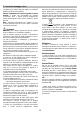
Installation
The minimum distance between the supporting surface for the
cooking equipment on the hob and the lowest part of the
range hood must be not less than 50cm from electric cookers
and 65cm from gas or mixed cookers.
If the instructions for installation for the gas hob specify a
greater distance, this must be adhered to.
Electrical connection
The mains power supply must correspond to the rating
indicated on the plate situated inside the hood. If provided with
a plug connect the hood to a socket in compliance with current
regulations and positioned in an accessible area. If it not fitted
with a plug (direct mains connection) or if the plug is not
located in an accessible area apply a double pole switch in
accordance with standards which assures the complete
disconnection of the mains under conditions relating to over-
current category III, in accordance with installation
instructions.
Warning! Before re-connecting the hood circuit to the mains
supply and checking the efficient function, always check that
the mains cable is correctly assembled.
Warning! Power cable replacement must be undertaken by
the authorised service assistance centre or similar qualified
person.
Mounting
Expansion wall plugs are provided to secure the hood to most
types of walls/ceilings. However, a qualified technician must
verify suitability of the materials in accordance with the type of
wall/ceiling. The wall/ceiling must be strong enough to take
the weight of the hood. Do not tile, grout or silicone this
appliance to the wall. Surface mounting only.
Operation
The cooker hood is provided with a key or pushbutton
control panel situated of the frontal part of the cooker
hood, depending on the basis of the cooker hood type in
possession. For proper operation consult the text below
and the relative illustration.
Use the high suction speed in cases of concentrated kitchen
vapours. It is recommended that the cooker hood suction is
switched on for 5 minutes prior to cooking and to leave in
operation during cooking and for another 15 minutes
approximately after terminating cooking.
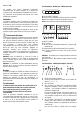
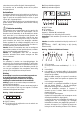
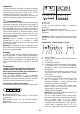
Functioning – Model with Keyboard
A
B
C
D
A. on/off light switch
B. on/off aspiration switch and minimum power selection
B+C. medium power selection aspiration switch
B+D. maximum power selection aspiration switch
a
a b-c
d
e
f
b-c-d-e
b-c-d-e
a
a
b
c
d
e
a. ON/OFF lighting
b. OFF motors
c. - d. - e. Minimum suction power (c.), medium (d.),
maximum (e.).
f. Operation warning light (where present).
Note: Some models only possess one suction Power.
Attention: the models with an electric valve are supplied with 3
keys:
(a) Light ON/OFF, (b) Electric Valve Closure and (c) Opening.
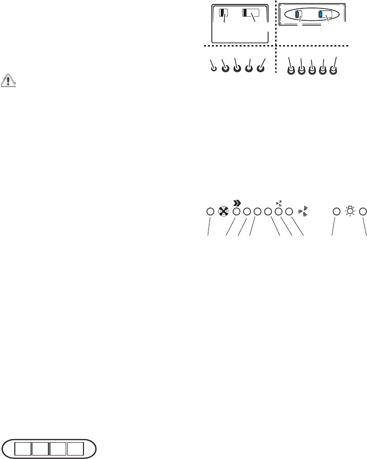
Functioning - 5-key electronic model
123OOI
FC
1234 567 8 9
1. Motor OFF button
2. ON button and motor speed selection button 1 - 2 - 3 - 1 -
2 - . . . .
3. Speed 1 LED
4. Speed 2 LED and metal grease filter saturation LED (in
this latter case, the LED will flash - See instructions on
grease filter cleaning).
Once the grease filters have been cleaned, press button
1 for about 3 seconds until you hear the acoustic signal
(beep): the LED 4 will now stop flashing.
5. Speed 3 LED and active carbon filter saturation LED (in
this latter case, the LED will flash - See instructions on
active carbon filter replacement).
Once you have replaced the charcoal filter, press button
1 for about 3 seconds until you hear the acoustic signal
(beep). LED 5 will now stop flashing.
Warning!
The active carbon filter saturation LED is not activated.
In order to activate the active carbon filter saturation
indicator, press buttons 2 and 7 simultaneously for 3
seconds. Initially, only LED 4 will flash, then after the 3
seconds have passed, LED 5 will also start flashing,
indicating that the active carbon filter saturation control
system is active.
To switch off the system, re-press the same two buttons:
after 3 seconds LED 5 will stop flashing and the device
will be switched off.
6. Intensive speed LED
7. Intensive speed ON switch
This speed should be used when the concentration of