
Installation Guide
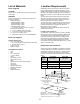

9
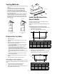
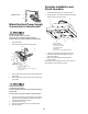
Make Electrical Power Supply
Connection to Hood Insert
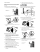
Electrical Shock Hazard
Disconnect power before servicing.
Replace all parts and panels before operating.
Failure to do so can result in death or electrical shock.
Disconnect power.
Locate terminal box inside of the hood insert.
Use UL listed wire connectors and connect black wires
(B) together.
Use UL listed wire connectors and connect white wires
(A) together.
Electrical Shock Hazard
Electrically ground blower.
Connect ground wire to green and yellow ground wire in
terminal box.
Failure to do so can result in death or electrical shock.
Connect green (or bare) ground wire from home power
supply to the green/yellow ground wire (D) in terminal
box using UL listed wire connectors.
Install terminal box cover.
Check that all light bulbs are secure in their sockets.
Reconnect power.
1.
2.
3.
4.
5.
6.
7.
8.
A
B
C
D
E
G
F
A.White wires
B. Black wires
C. UL listed wire connectors
D. Green, bare or yellow/green wires
E.Home power supply
F. UL listed or CSA approved ¹⁄2” (1.3 cm) strain relief
G. Ground Wire tab
B
A
A. Wiring Box Connector
B. Hood Insert Connector
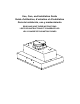
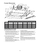
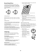
Complete Installation and
Check Operation
Install grease lters. See the “Cleaning” section.
Check operation of the Hood Insert blower and lights.
See the “Hood Insert Use” section.
If the hood insert does not operate, check to see
whether a circuit breaker has tripped or a hous
hold fuse has blown.
Disconnect power supply and check that the
wiring is correct.
NOTE: To get the most efcient use from your new hood
insert, read the “Hood Insert Use” section.
1.
2.
3.
4.
A. Halogen lights
B. Halogen light switch
C. Blower control switche
D. Grease lter handle
E. Grease lter
F. Filter Spacer (Only for EAR628SS model)
A A
B C
A
A
F
D E