
Installation instructions


7
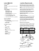
Venting Methods
The hood exhaust opening has a 10” diameter round vent
outlet.
On installations using the 600 CFM Blower Motor
Systems, 8” round vent system is recommended.
On installations using the 1200 CFM Blower Motor
Systems, a 10” round vent system should be used.
You can use a smaller round vent system , but there will
be a louder sound level.
NOTE: Flexible vent is not recommended. Flexible vent
creates back pressure and air turbulence that greatly
reduce performance. Vent system can terminate either
through the roof or wall. To vent through the wall, a 90°
elbow is needed.
Prepare the Location
Disconnect power.
Determine which venting method to use: roof or wall
exhaust.
Select a at surface for assembling the hood insert.
Place covering over that surface.
It is recommended that the vent system be installed
before hood is installed.
Before making cutouts, make sure there is proper
clearance within the ceiling or wall for exhaust vent.
Hood insert should be installed a minimum 24” (61 cm)
above an electric cooktop surface and 30” (76.2 cm)
above a gas cook top surface. The maximum
recommended height over both cook tops is 36” (91.44
cm).
Check that all installation parts have been removed
from the shipping carton.
Using 2 or more people, lift hood insert onto covered
surface.
Remove the lters. See the “Cleaning” section.
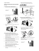
Stainless Steel Hood Spacer Installation
You can elongate 1.5” of your range hood width (¾” per side),
installing the stainless steel spacers included with your range
hood.
Unpack the spacer and take off the protective.
Put each one on the right and the left side
Fasten hood spacer using four 5 x 45 mm screws to the
hood cabinet and tighten securely.
•
•
•
•
1.
2.
3.
•
•
•
•
4.
5.
1.
2.
3.
A
B
B
A
Roof venting
A. 10” (25.4 cm) round vent
B. Roof cap
Wall Venting
A. 10” (25.4 cm) round vent
B.Wall cap
Install Range Hood into
Hood Cabinet
The range hood attaches to the hood cabinet using four
mounting screws and washers.
NOTE: Hood cabinet must be capable of supporting 75 lb
(34 kg).
Prepare Range hood for mounting into cabinet
Mark the locations for the four mounting screws on the
hood cabinet as shown below.
Using a ⅛” (3 mm) drill bit, drill the 4 holes.
A
B
C
D
E
F
Mark the cutout for the rectangular clearance hole for the
upper range hood motor housing as shown.
Using a jigsaw or keyhole saw, cut out the rectangular
clearance hole for the upper range hood housing.
1.
2.
3.
4.
A. Centerline
Mounting
holes
A. Centerline
MOUNTING HOLE DIMENSIONS
Hood
Insert
DIM B DIM C DIM D DIM E DIM F
EAR628SS
5½” (14 cm) 11” (28 cm) 12
5
⁄32” (30.9 cm) 24
5
⁄16” (61.8 cm) Ø1/8” (3mm)
EAR134SS
6” (15.5 cm) 10
1
⁄16” (25.6 cm) 14
15
⁄16” (38 cm) 29
13
⁄16” (75.8 cm) Ø1/8” (3mm)
EAR140SS
6” (15.5 cm) 10
1
⁄16” (25.6 cm) 14
15
⁄16” (38 cm) 29
13
⁄16” (75.8 cm) Ø1/8” (3mm)
EAR146SS
6” (15.5 cm) 10
1
⁄16” (25.6 cm) 14
15
⁄16” (38 cm) 29
13
⁄16” (75.8 cm) Ø1/8” (3mm)
UPPERHOOD MOTOR HOUSINGS DIMENSIONS
Hood
Insert
DIM B DIM C DIM D DIM E
EAR628SS
4
13
/16” (12.2 cm) 12
7
⁄8” (32.7 cm) 11¼” (28.57 cm) 22½” (57.15 cm)
EAR134SS
4
13
/16” (12.2 cm) 12
7
⁄8” (32.7 cm) 14” (35.56 cm) 28” (71.12 cm)
EAR140SS
4
13
/16” (12.2 cm) 12
7
⁄8” (32.7 cm) 14” (35.56 cm) 28” (71.12 cm)
EAR146SS
4
13
/16” (12.2 cm) 12
7
⁄8” (32.7 cm) 14” (35.56 cm) 28” (71.12 cm)
Hood spacer