
Inline Blower Manual


5
Location Requirements
IMPORTANT: Observe all governing codes and ordinances.
Have a qualified technician install the in-line blower motor
system.
All openings in the ceiling and wall where the in-line blower
motor system will be installed must be sealed.
For Mobile Home Installations
The installation of this in-line blower motor system must
conform to the Manufactured Home Construction Safety
Standards, Title 24 CFR, Part 328 (formerly the Federal
Standard for Mobile Home Construction and Safety, Title
24, HUD, Part 280) or when such standard is not applicable,
the standard for Manufactured Home Installation 1982
(Manufactured Home Sites, Communities and Setups) ANSI
A225.1/NFPA 501A*, or latest edition, or with local codes.
Product dimensions
14
7
⁄8”
(20 cm)
TOP (OUTLET) VIEW
BOTTOM (INLET) VIEW
3
3
⁄8”
(8.6 cm)
12
15
⁄16”
(32.9 cm)
26
1
⁄8”
(66.4 cm)
14
11
⁄16”
(37.3 cm)
24
3
⁄4”
(62.9 cm)
3
3
⁄8”
(8.6 cm)
14
7
⁄8”
(20 cm)
16
1
⁄8”
(41 cm)
Venting Requirements
• The vent system must terminate to the outdoors.
• Do not terminate the vent system in an attic or other
enclosed area.
• Do not use 4” (10.2 cm) laundry-type vent or wall caps.
• Use round, metal vent only. Rigid metal vent is
recommended. Plastic or metal foil vent is not
recommended.
• The length of the vent system and number of elbows
should be kept to a minimum to provide ecient
performance.
For the most efficient and quiet operation:
• Use no more than three 90° elbows.
• Make sure there is a minimum of 24” (61.0 cm) of straight
vent between the elbows if more than 1 elbow is used.
• Do not install 2 elbows together.
• Use clamps to seal all joints in the vent system.
• The vent system must have a damper.
• Use weatherproof caulking to seal the exterior wall or roof
opening around the cap.
• The size of the vent should be uniform.
Cold weather installations
An additional backdraft damper should be installed to
minimize backward cold air flow. A thermal break should be
installed to minimize conduction of outside temperatures as
part of the vent system. The damper should be on the cold air
side of the thermal break.
The thermal break should be as close as possible to where the
vent system enters the heated portion of the house.
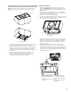
Typical In-line Blower System Installations
A 8” (20.32 cm) - 10” (25.4 cm) round vent system is needed
for installation (not included). The in-line blower system inlet
and outlet openings are 8” (20.32 cm) - 10” (25.4 cm) round.
The exhaust (outlet) opening on the range hood must also be
8” (20.32 cm) - 10” (25.4 cm) round.
NOTE: Flexible vent is not recommended. Flexible vent
creates back pressure and air turbulence that greatly reduce
performance.
The vent system can terminate either through the roof or wall.
NOTE: Plywood may be used as a mounting base to span
open areas between ceiling joists and rafters. If used, be sure
to use plywood capable of supporting the weight of the in-
line blower system (50 lb [22.6 kg]).
A
B
C
D
E
E
A. Mount on top of ceiling
joists.
B. Mount from cross-members
tied to trusses.
C. Duct horizontal; mount to
cross-members tied to
trusses.
D. Mount on underside of roof
rafters.
E. Plywood