
Installation Guide


14
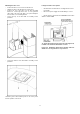
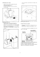
Connecting the ductwork
• Install ductwork, making connections in the direction of
airflow as illustrated.
• Push duct over the exhaust outlet.
• Wrap all duct joints and the flange connections with duct
tape for an airtight seal.
• Make the same connection in the wall or ceiling vent
exit.
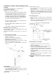
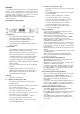
Air deflector installation
• Assemble the air deflector with the duct cover bracket
with 4 assembly screws provided as shown.
• Measure from the bottom of the air deflector to the
bottom of the hood outlet, as shown.
• Cut the duct at the measured size.
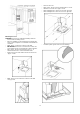
• Uninstall the air deflector removing the 4 assembly
screws.
• Slip the duct onto the bottom of the deflector.
• Place the assembled deflector and duct over the exhaust
outlet from the hood.
• Assemble the air deflector to the duct cover bracket with
4 assembly screws provided as shown.
Electrical connection
WARNING
Electrical Shock Hazard
Warning: Turn off power circuit at the service panel
before wiring this unit.
120 VAC, 15 or 20 Amp circuit required.
ELECTRICAL GROUNDING INSTRUCTIONS
THIS APPLIANCE IS FITTED WITH AN ELECTRICAL
JUNCTION BOX WITH 3 WIRES, ONE OF WHICH
(GREEN/YELLOW) SERVES TO GROUND THE
APPLIANCE. TO PROTECT YOU AGAINST
ELECTRIC SHOCK, THE GREEN AND YELLOW WIRE
MUST BE CONNECTED TO THE GROUNDING WIRE
IN YOUR HOME ELECTRICAL SYSTEM, AND IT
MUST UNDER NO CIRCUMSTANCES BE CUT OR
REMOVED.
Failure to do so can result in death or electrical
shock.
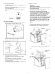
Facing the front of the range hood, remove the left
knockout and the Junction box cover and install the
conduit connector (cULus listed) in junction box.
• If not already done, install 1/2” conduit connector in j-
box.