Use, Care, and Installation Guide READ AND SAVE THESE INSTRUCTIONS
EN Contents page 1 English Contents Important safety Notice ..............................................................................................................................................3 Electrical & Installation requirements ......................................................................................................................4 Electrical requirements .........................................................................................................................
READ AND SAVE THESE INSTRUCTIONS Important safety Notice WARNING CAUTION TO REDUCE THE RISK OF INJURY TO PERSONS, IN THE EVENT OF A RANGE TOP GREASE FIRE, OBSERVE THE FOLLOWING: a) SMOTHER FLAMES with a close-fitting lid, cookie sheet, or other metal tray, then turn off the gas burner or the electric element. BE CAREFUL TO PREVENT BURNS. If the flames do not go out immediately, EVACUATE AND CALL THE FIRE DEPARTMENT. b) NEVER PICK UP A FLAMING PAN - you may be burned.
Electrical & Installation requirements Electrical requirements Before installing the hood IMPORTANT 1. For the most efficient air flow exhaust, use a straight run or as few elbows as possible. CAUTION: Vent unit to outside of building, only. Observe all governing codes and ordinances. It is the customer’s responsibility: To contact a qualified electrical installer.
List of Materials Parts supplied Parts not supplied Removing the packaging Optional Accessories CAUTION! Remove carton carefully, Wear gloves to protect against sharp edges. • WARNING! Remove the protective film covering the product before putting into operation. • Hood canopy assembly with blower, transition. • Lamp already installed. • Grease filter. • Glass Canopy • Duct cover. • Hardware bag with: • Plastic Gasket. • Template.
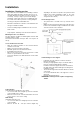
Dimensions and Clearances 6
Ducting Options and Examples Closely follow the instructions set out in this manual. All responsibility, for any eventual inconveniences, damages or fires caused by not complying with the instructions in this manual, is declined. Venting methods The hood is equipped with a transition B for discharge of fumes to the outside (Ducting version). Should it not be possible to discharge cooking fumes and vapour to the outside, the hood can be used in the Ductless (Recirculating) version.
Installation Installation - Ducting version • If possible, disconnect and move freestanding or slide-in range from cabinet opening to provide easier access to rear wall. Otherwise put a thick, protective covering over countertop, cooktop or range to protect from damage and debris. Select a flat surface for assembling the unit. Cover that surface with a protective covering and place all canopy hood parts and hardware in it.
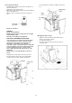
Mounting the hood WARNING: 2 people are required to lift and position the hood onto the mounting screws. • Place the template on the wall along the horizontal line, make sure the template is leveled and centered with the centerline. • Mark “upper” screw holes locations in the wall. • IMPORTANT. Check to be sure that hole locations are leveled and correctly centered by the vertical centerline. • Drive “upper” wood screws by hand. Leave ¼ “ of distance between the screw head and the wall.
Connecting the ductwork • Install ductwork, making connections in the direction of airflow as illustrated. • Push duct over the exhaust outlet. • Wrap all duct joints and the flange connections with duct tape for an airtight seal. • Make the same connection in the wall or ceiling vent exit. • If not already done, install 1/2” conduit connector in jbox. Electrical connection WARNING Electrical Shock Hazard Warning: Turn off power circuit at the service panel before wiring this unit.
Mounting the duct cover If range hood does not operate: • • • • • Position the duct cover over the mounted hood. Slide the bottom of the duct into the canopy area. Position the top of the duct over the duct mounting bracket. If a telescopic duct cover is used, grab the upper part of the telescopic duct cover, pull it and place it in the duct cover mounting bracket. Secure the top of the duct with 2 assembly screws provided. • Check that the circuit breaker is not tripped or the house fuse blown.
Installation - Ductless (Recirculating) version If ductwork will vent to rear: • Use a level to draw a line straight up from the centerline on the template. • Measure at least 23 - 3/4" (the measure might vary dependig on the elbow used) above the pencil line that indicates the bottom installation height, to the circle center of an 8-½” diameter duct hole (Hole may be elongated for duct elbow). CAUTION To install the hood in this version, first purchase the Ductless Recirculating Kit.
Mounting the hood WARNING: 2 people are required to lift and position the hood onto the mounting screws. • Place the template on the wall along the horizontal line, make sure the template is leveled and centered with the centerline. • Mark “upper” screw holes locations in the wall. • IMPORTANT. Check to be sure that hole locations are leveled and correctly centered by the vertical centerline. • Drive “upper” wood screws by hand. Leave ¼ “ of distance between the screw head and the wall.
Electrical connection Connecting the ductwork • Install ductwork, making connections in the direction of airflow as illustrated. • Push duct over the exhaust outlet. • Wrap all duct joints and the flange connections with duct tape for an airtight seal. • Make the same connection in the wall or ceiling vent exit. WARNING Electrical Shock Hazard Warning: Turn off power circuit at the service panel before wiring this unit. 120 VAC, 15 or 20 Amp circuit required.
Mounting the glass canopy • • • • With the hood mounted on the wall slide the glass canopy over the glass supports. Insert the glass brackets. Insert two screws into the bracket holes, drive the screws by hand. Install the grease filter and turn power on at service panel. Check operation of the hood. Mounting the duct cover • • • • Secure the bottom of the duct with 2 assembly screws provided. Position the duct cover over the mounted hood. Slide the bottom of the duct into the canopy area.
Description of the hood & Controls 1. 2. 3. 4. 5. 6. 7.
5. “+” Button. Speed Increase / ON Controls • This button is used to increase the fan speed, or turn ON the fan. • The fan will turn ON if the “+” button is pressed and the hood was OFF. • If the fan is at first speed and the “+” button is pressed, the fan will be set to second speed. • If the fan is at second speed and the “+” button is pressed, the fan will be set to third speed. • If the fan is at third speed and the “+” button is pressed, the fan will be set to fourth speed.
Charcoal filter inclusion and exclusion (Recirculating accessories) • The charcoal filter inclusion or exclusion can be set by pressing the “+” and “-” buttons at the same time for 5 seconds. • The Inclusion or exclusion of charcoal filter must be selected while the lamps and the motor are OFF. • When the charcoal filter has been excluded, the charcoal filter alarm is disabled.
Maintenance ATTENTION! Before performing any maintenance operation, isolate the hood from the electrical supply by switching off at the connector and removing the connector fuse. Or if the appliance has been connected through a plug and socket, then the plug must be removed from the socket. Cleaning The cooker hood should be cleaned regularly (at least with the same frequency with which you carry out maintenance of the fat filters) internally and externally.