
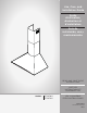
Owner Manual


7
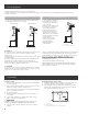
4 Mark centers of the fastener locations through the
template to the wall.
IMPORTANT: All screws must be installed into wood.
If there is no wood to screw into, additional wall framing
supports may be required.
5 Remove the template.
6 Drill
3
⁄16” (4.8 mm) pilot holes at all locations where screws
are being installed into wood.
7 Install the 2 - 5 x 45 mm mounting screws. Leave a
1
⁄4”
(6.4 mm) gap between the wall and the back of the screw
head to slide range hood into place.
1
⁄4”
(6.4 mm)
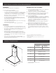
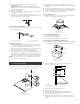
Vent cover bracket installation
1 Attach vent cover bracket to wall flush to the ceiling using
2 - 5 x 45 mm screws.
A
C
D
B
A. 8 x 40 mm anchors
B. Centerline on wall
C. Vent cover support bracket
D. 5 x 45 mm screws
Complete preparation
1 Determine and make all necessary cuts in the wall for the
vent system. Install the vent system before installing the
hood. See “Venting Requirements” section.
2 Determine the required height for the home power supply
cable and drill a 1¼” (3.2 cm) hole at this location.
3 Run the home power supply cable according to the
National Electrical Code or CSA Standards and local codes
and ordinances. There must be enough ½” conduit and
wires from the fused disconnect (or circuit breaker) box to
make the connection in the hood’s electrical terminal box.
NOTE: Do not reconnect power until installation is complete.
4 Use caulk to seal all openings.
Install Range Hood
1 Using 2 or more people, hang range hood on 2 mounting
screws through the mounting slots on back of hood.
A
C
B
A. Mounting screws
B. Mounting slots
C. Lower mounting screws
1
2 Mark with a pencil the lower mounting holes location.
3 Uninstall the hood assembly, and drill pilot holes at marked
locations.
4 Hang the range hood again on 2 upper mounting screws.
5 Level the range hood and tighten upper mounting screws.
6 Install 2 - 5 x 45 mm lower mounting screws and tighten.
Use the optional wall anchors if needed.
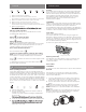
Connect Vent System
1 Install transition on top of hood (if removed for shipping)
with 2 - 3.5 x 9.5 mm sheet metal screws.
A
B
A. Vent transition
B. 3.5 x 9.5 mm screw
For vented installations only:
1 Fit vent system transition place.
2 Seal connetion with clamps.
3 Check tha brackdraft dampers work propely.
For non vented (recirculating) installation only:
1 Assemble the air deflector with the duct cover bracket with
2 - assembly screws provided with the Recirculating Kit.
A
B
B
C
A. Vent cover bracket
B. 2.9 X 6.5 mm screw
C. Deflector
2 Measure from the bottom of the air deflector to the
bottom of the hood outlet.
C
A
B
D
E
x
A. Air deflector
B. Vent clamp
C. X = length to cut duct cover
D. Duct cover
E. Exhaust outlet
3 Cut the duct to the measured size “X.”
4 Remove the air deflector.
5 Slide the duct onto the bottom of the air deflector.
6 Place the assembled air deflector and duct over the
exhaust outlet from the hood.
7 Reassemble the air deflector to the duct cover bracket
with the two assembly screws. Seal connections with vent
clamps.