
Installation Instructions


9
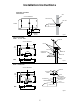
NOTE: The3¹⁄4”x10”(8.3x25.4cm)rectangularvent
connectorcanbeinstalledupto1”(2.5cm)oneithersideof
the hood center to accommodate off center ductwork.
If a vent damper is installed with a wall cap with damper,
check to make sure they do not interfere with each other.
Removetheventconnectordamperapiftheyinterfere.
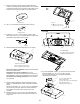
Non-ducted (recirculating) installations - No vent
attachments. The ERS230, ENM230 and ENM236 series
models requires the removal of the recirculation cover plate.
Remove the two screws from the recirculation cover plate and
remove.
■
■
A. Screws
B. Recirculation cover plate
A
B
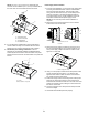
Power Supply Cable Installation
For direct wire installations, run the home power supply cable
according to the National Electric Code or CSA standards
and local codes and ordinances. There must be enough
wiringfromthefuseddisconnect(orcircuitbreaker)boxto
make the connection in the hood electrical terminal box.
For optional power supply cord kit installations, follow the
instructions included with the power supply cord kit.
NOTE: Do not reconnect power until the installation is
complete.
Remove the screw from the terminal box cover. Remove
terminal box cover and set aside.
Remove the power supply knockout from the top or rear of
theventhood(dependingontheincominglocationofyour
homepowersupplycable)andinstallaULListedorCSA
approved¹⁄2” strain relief.
Using2ormorepeople,liftthehoodintonalposition.Feed
enough electrical wire through the ½” UL listed or CSA
approved strain relief to make connections in the terminal
box. Tighten the strain relief screws.
Position the range hood so that the large end of the keyhole
slots are over the mounting screws. Then push the hood
toward the wall so that the screws are in the neck of the slots.
Tighten the mounting screws, making sure the screws are in
the narrow neck of slots.
Connect ventwork to hood. Seal joints with clamps to make
secure and airtight.
Check that back draft dampers work properly.
1.
2.
3.
4.
5.
6.
7.
A. Terminal box cover
B. Screw
A
B
A. Power supply knockout
A
B
A
B
D
C
Vertical connector
6.5 x 9.5 mm screws
Vent knockouts
Horizontal connector
A.
B.
C.
D.
A
B
model: ENM
models:ESN
EFS
ERS