Use, Care, and Installation Guide Guide d’utilisation, d’entretien et d’installation Guía de instalación, uso y mantenimiento READ AND SAVE THESE INSTRUCTIONS LISEZ CES INSTRUCTIONS ET CONSERVEZ-LES LEA Y GUARDE ESTAS INSTRUCCIONES
English French Spanish Contents page 2 Sommaire page 22 Contenido página 43 English Contents Important safety Notice..............................................................................................................................................3 Electrical & Installation requirements ......................................................................................................................4 Electrical requirements ...........................................................
READ AND SAVE THESE INSTRUCTIONS Important safety Notice WARNING CAUTION TO REDUCE THE RISK OF INJURY TO PERSONS, IN THE EVENT OF A RANGE TOP GREASE FIRE, OBSERVE THE FOLLOWING: a) SMOTHER FLAMES with a close-fitting lid, cookie sheet, or other metal tray, then turn off the gas burner or the electric element. BE CAREFUL TO PREVENT BURNS. If the flames do not go out immediately, EVACUATE AND CALL THE FIRE DEPARTMENT. b) NEVER PICK UP A FLAMING PAN - you may be burned.
Electrical & Installation requirements Electrical requirements Before installing the hood IMPORTANT 1. For the most efficient air flow exhaust, use a straight run or as few elbows as possible. CAUTION: Vent unit to outside of building, only. Observe all governing codes and ordinances. It is the customer’s responsibility: To contact a qualified electrical installer.
List of Materials Parts supplied Parts not supplied CAUTION! Remove carton carefully, Wear gloves to protect against sharp edges. Optional Accessories Removing the packaging Ductless Recirculating Kit To be used only in the Ductless (Recirculating) version includes: charcoal filter, charcoal filter support and fixing bracket, deflector WARNING! Remove the protective film covering the product before putting into operation. Hood structure assembly with blower, transition. 4 Lamps already installed.
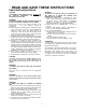
Dimensions and Clearances 12 - 1/8” 13 - 3/16” * Mín 32 - 13/32” *Max 52 - 13/32“ ** Mín 32 - 13/32” ** Max 46 - 13/32“ 2 - 3/8” 36” - 42” 27” * Ductless (Recirculating) version ONLY 6
Ducting Options and Examples Closely follow the instructions set out in this manual. All responsibility, for any eventual inconveniences, damages or fires caused by not complying with the instructions in this manual, is declined. Venting methods The hood is equipped with a transition B for discharge of fumes to the outside (Ducting version). Should it not be possible to discharge cooking fumes and vapour to the outside, the hood can be used in the Ductless (Recirculating) version.
Installation Installation - Ducting version IMPORTANT Framing must be capable of supporting 150lbs. 1. Pre-installation calculations K = Kitchen Height C = Counter Height (36" standard) P = Prefered Height of Hood Bottom above counter H = Hood height your installation H =K – C – P S = Chimney Structure Height, your installation. S = H - 1" 3/8. a) Select a hood preference height P that is comfortable for the user. b) Calculate Hood height your installation H = K-C-P.
Place the template in the ceiling considering the instructions for ceiling support structures. Always consider the front of hood legend when playing the templete on the ceiling. It will define the control’s location. Attach the 4 lower vertical supports (A) to the hood with 16 screws Then attach the lower horizontal support (B) whit 8 screws (inf). B A Attach the 4 upper vertical supports (sup) (c) whit 16 screws to adjust he desired distance.
Connecting the ductwork Install ductwork, making connections in the direction of airflow as illustrated. Push duct over the exhaust outlet. Wrap all duct joints and the flange connections with duct tape for an airtight seal. Make the same connection in the wall or ceiling vent exit. If not already done, install 1/2” conduit connector in jbox. Electrical connection WARNING Electrical Shock Hazard Warning: Turn off power circuit at the service panel before wiring this unit.
The lower duct cover shall be secured to rangehood by 4 screws. Attach the vertical duct cover supports using 4 screws. Place upper duct covers sliding through until spring sounds “click”. Then verify. Install the grease filter and turn power on at service panel. Check operation of the hood. If range hood does not operate: Check that the circuit breaker is not tripped or the house fuse blown. Disconnect power supply. Check that wiring is correct.
Installation - Ductless (Recirculating) version IMPORTANT Recirculating kit sold separately. To purchase it, please dial the following toll free number 1-888-732-8018 and request the KIT02198 for island hoods. 1. Pre-installation calculations K = Kitchen Height C = Counter Height (36" standard) P = Prefered Height of Hood Bottom above counter H = Hood height your installation H =K – C – P S = Chimney Structure Height, your installation. S = H - 1" 3/8.
Place the template in the ceiling considering the instructions for ceiling support structures. Always consider the front of hood legend when playing the template on the ceiling. It will define the control’s location. Attach the 4 lower vertical supports (A) to the hood with 16 screws Then attach the lower horizontal support (B) whit 8 screws (inf). B A Attach the 4 upper vertical supports (sup) (c) whit 16 screws to adjust he desired distance.
Air deflector installation Assemble the air deflector with the upper horizontal support with 2 assembly screws. Cut the duct at the measured size. Slip the duct onto the bottom of the deflector. Place the duct over the exhaust outlet from the hood. Use duct tape to seal the deflector and at the exhaust outlet from the hood. Measure from the bottom of the air deflector to the bottom of the hood outlet, as shown.
Place lower duct covers using one plastic bracket at each vertex (4 needed). If not already done, install 1/2” conduit connector in jbox. The lower duct cover shall be secured to rangehood by 4 screws. Attach the vertical duct cover supports using 4 screws. Install the grease filter and turn power on at service panel. Check operation of the hood. If range hood does not operate: Place upper duct covers sliding through until spring sounds “click”. Then verify.
Description of the hood & Controls 1. 2. 3. 4. 5. 6.
5. “+” Button. Speed Increase / ON t This button is used to increase the fan speed, or turn ON the fan. t The fan will turn ON if the “+” button is pressed and the hood was OFF. t If the fan is at first speed and the “+” button i s pressed, the fan will be set to second speed. t If the fan is at second speed and the “+” button is pressed, the fan will be set to third speed. t If the fan is at third speed and the “+” button is pressed, the fan will be set to fourth speed.
Grease filter saturation alarm (Optional) t After thirty fan functional hours, the display will show “Grease Filter ” if the fan is active. When this icon is shown in the display, the grease filters installed are required to be washed. t To reset the grease filter saturation alarm the user must press the “+” button for 5 seconds, after this action the icon “Grease filter ” is not displayed, and the hood has the normal display operation.
Maintenance ATTENTION! Before performing any maintenance operation, isolate the hood from the electrical supply by switching off at the connector and removing the connector fuse. Or if the appliance has been connected through a plug and socket, then the plug must be removed from the socket. Cleaning Do not spray cleaners directly to the control while cleaning the Hood.