
Installation Sheet


8
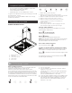
Electrical Connection
I WARNING
ELECTRICAL SHOCK HAZARD.
I WARNING
DISCONNECT POWER BEFORE SERVICING.
REPLACE ALL PARTS AND PANELS BEFORE OPERATING.
FAILURE TO DO SO CAN RESULT IN DEATH OR
ELECTRICAL SHOCK.
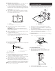
1 Disconnect power.
2 Remove terminal box cover.
3 Remove the knockout in the terminal box cover and install
a UL listed or CSA approved
1
⁄2” strain relief.
4 Run home power supply cable through strain relief, into
terminal box.
A
B
C
D
E
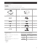
A. Home power supply cable
B. UL listed or CSA approved
strain relief
C. Black wires
D. UL listed wire connectors
E. White wires
F. Green (or bare) and
yellow-green ground wires
5 Use UL listed wire connectors and connect black wires
(C) together.
6 Use UL listed wire connectors and connect white wires (E)
together.
I WARNING
ELECTRICAL SHOCK HAZARD.
I WARNING
ELECTRICALLY GROUND BLOWER.
CONNECT GROUND WIRE TO GREEN AND YELLOW
GROUND WIRE IN TERMINAL BOX. FAILURE TO DO SO CAN
RESULT IN DEATH OR ELECTRICAL SHOCK.
7 Connect green (or bare) ground wire from home power
supply to yellow-green ground wire (F) in terminal box
using UL listed wire connectors.
8 Tighten strain relief screw.
9 Install terminal box cover.
10 Check that all light bulbs are secure in their sockets.
11 Reconnect power.
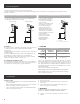
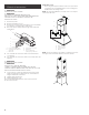
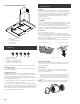
Install duct covers
• When using both upper and lower vent covers, push lower
cover down onto hood and lift upper cover to ceiling and
install with two mounting screws.
NOTE: For vented installations, the upper vent cover may be
reversed to hide slots.
C
A
B
C
D
A. Upper vent cover
B. Lower vent cover
C. 4 x 8 mm screws
D. Bracket
NOTE: To prevent scratches, lay paper or a kitchen towel over
the edges of the lower flue duct to protect the surface.