
manual


13
instructions.
Warning! Before re-connecting the hood circuit to the mains
supply and checking the efficient function, always check that
the mains cable is correctly assembled.
Mounting
Expansion wall plugs are provided to secure the hood to most
types of walls/ceilings. However, a qualified technician must
verify suitability of the materials in accordance with the type of
wall/ceiling. The wall/ceiling must be strong enough to take
the weight of the hood. Do not tile, grout or silicone this
appliance to the wall. Surface mounting only.
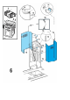
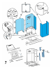
Assembling the deflector (Fig. 6 - 3 parts – only for filter
version):
The three parts should be fixed with 2 screws, the deflector
extension is adjustable and should correspond to the width of
the chimney flue support, to which it is then fixed.
Fig. 5-6-7
During electrical connection ensure the power supply is
disconnected at the domestic main switch.
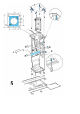
1. Adjust extension of the hood support structure, as the
final height of the hood depends on this, and remember
that with installation completed the hood must be at least
50 cm above the cook-top for electric cookers and 75 cm
for gas or mixed cookers.
2. a. Fix the two sections of the structure using 8 screws.
b. If the hood is provided with extensions longer than the
minimum, fit the reinforcement bracket S to the frame,
using 4 screws.
3. Place the ceiling hole diagram directly above the cook-
top (the center of the diagram must match the center of
the cook-top and the edges must be parallel to the sides
of the cook-top – the side of the diagram with the wording
FRONT corresponds to the control panel side). Prepare
the electrical connection.
4. Drill as shown (6 holes for 6 wall plugs – 4 plugs for
fixture), screw the outer screws leaving a space of about
1 cm. between the screw head and the ceiling.
5. Fit an exhaust pipe inside the truss and connect it to the
motor compartment connection ring (exhaust pipe and
fixing brackets are not supplied).
6. Hook the frame onto the 4 screws (see step 4).
CAUTION! The side of the truss with connection box
corresponds to the side of the control panel with hood
assembled.
7. Tighten the 4 screws.
8. Insert and tighten another 2 screws in the remaining free
holes for secure fixing.
9. Carry out the electrical connection to the mains power
supply, only turn on the power supply upon completion of
assembly.
10. Hook the hood onto the truss, ensuring it fits properly – to
hook the hood onto the truss partially tighten 4 screws
(see also step 12).
11. Secure the hood to the truss using two screws; this will
also help center the two sections.
12. Tighten the 4 screws securing the truss to the hood.
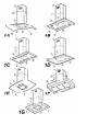
13. For extractor versions (13A), connect the other end of the
exhaust pipe to the flue.
For filter versions (13F), fit deflector F to the truss and
secure it to the bracket supplied using 4 screws, then
connect the exhaust pipe to the connection ring located
on the deflector.
14. Fit the nuts with fixing hooks supplied inside the top and
bottom sections of the flues at the rectangular slots. A
total of 14 nuts must be fitted.
15. Join the two top sections of the flue to cover the truss so
that one of the slots on the sections is situated on the
same side of the control panel and the other on the
opposite side. Screw the two sections together with 8
screws (4 each side- see the plan diagram for joining the
two sections).
16. Fix the top flue assembly to the truss, near the ceiling,
with two screws (one each side).
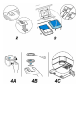
17. Carry out electrical connection of control panel and bulbs.
Warning! Make connections taking care to insert the
connectors in the right way.
18. Join the two bottom sections of the flue covering the truss
using 6 screws (3 each side, see the plan diagram for
joining the two sections).
19. Insert the bottom section of the flue in its seat so that it
completely covers the motor compartment and electrical
connection box, then ensure it from inside the hood using
two screws.
20. Apply the 2 tabs (supplied) to cover the fixing points of
the bottom flue (CAUTION! THE BOTTOM FLUE TABS
ARE THE NARROWER AND SHALLOWER ONES).
The wider and deeper tabs are those used for the top
flue, and must be cut to size.
For models shown in Fig. 1H: A double face adhesive
strip is supplied with the hood, cut it in 8 pieces and use it
to fix the 4 tabs.
21. Turn the mains power on again at the central electrical
panel and check for correct hood operation.
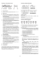
Description of the hood
Fig. 1
1. Control panel
2. Grease filter
3. Grease filter release handle
4. Halogen lamp
5. Vapour catcher
6. Telescopic chimney
7. Air outlet (used for filter version only)
Operation
Use the high suction speed in cases of concentrated kitchen
vapours. It is recommended that the cooker hood suction is
switched on for 5 minutes prior to cooking and to leave in
operation during cooking and for another 15 minutes
approximately after terminating cooking.