Eliko RTLS Installation Guide Tallinn 2021
CONTENTS DOCUMENT SCOPE AND PURPOSE.................................................................... 3 TERMINOLOGY........................................................................................... 3 1. SYSTEM COMPONENTS AND CONNECTIVITY..................................................... 4 2. ANCHOR INSTALLATION............................................................................ 6 a. Anchor coordinate measurement........................................................... 7 b.
DOCUMENT SCOPE AND PURPOSE This installation guide is designed to help users install the Eliko RTLS system. TERMINOLOGY GUI – Graphical User Interface LoS – Line of sight NLoS – Non-line of sight PoE – Power over Ethernet RTLS – Real-Time Location System UWB – Ultra-Wideband Aiandi 13/1 | Tallinn 12918 | Estonia Tel: +372 6599 881 | support@eliko.ee | www.eliko.
1. SYSTEM COMPONENTS AND CONNECTIVITY The Eliko RTLS consists of: • Eliko RTLS Anchors – Anchors can be used in two different configurations: • Anchors in standard configuration use a Power over Ethernet (PoE) connector for both power and data transmission (note: anchors can also be powered by micro-USB, and Ethernet can be used for data transmission only). All Ethernet cables starting with cat 5 are compatible with the Eliko RTLS system. Eliko recommends using 8 core Ethernet cables.
Figure 1. A small-scale Eliko RTLS network with ethernet connectivity. Figure 2. A small-scale Eliko RTLS network with Wi-Fi connectivity. Aiandi 13/1 | Tallinn 12918 | Estonia Tel: +372 6599 881 | support@eliko.ee | www.eliko.
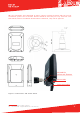
2. ANCHOR INSTALLATION In order to cover the entire tracking area, it is usually best to install the anchors at an elevated position, misaligned and close to the edges of the tracking area (but not in the corners). In special rooms, such as corridors, the anchors should be placed using a trapezoid or rhombus pattern. The anchors should be placed on the wall using Eliko RTLS wall mounts (see Figure 5).. The wall mounts have moving heads that you can use to adjust the anchor position.
are no objects close to the anchors blocking the LoS. Although the performance of the anchor is very similar in all directions, in more difficult scenarios it is recommended that the anchor side with the Ethernet port faces the direction of least interest. In square-shaped rooms it is best to mount anchors to the ceiling as displayed in Figure 3; if this is not possible, then use the alternative option displayed in Figure 3.
NB! The coordinate axes displayed in Figure 4 don’t necessarily match with the overall coordinate system. The correction factors should be used only for very accurate (less than 50 cm) anchor coordinate measurements. Otherwise, they can be ignored. thread for universal fixtures micro USB ethernet cable Figure 5. Eliko anchor and anchor mount Aiandi 13/1 | Tallinn 12918 | Estonia Tel: +372 6599 881 | support@eliko.ee | www.eliko.
3. ELIKO RTLS SERVER SETUP a. Starting up the Eliko RTLS server The Eliko RTLS Server is an Ubuntu Linux machine with dual ethernet interfaces – one for the anchor network (Anchor’s Network) and the other for integration with the client’s system (Client’s Network). Additionally, the RTLS Server includes an optional integrated Wi-Fi module, so connections to the RTLS anchors and/or to the client’s application logic may also be done wirelessly. NB! Before power-up, attach Wi-Fi antennas to the server.
connection just a couple of seconds after clicking the “connect” button, without waiting for the progress indicator to finish. When connected via Wi-Fi, you can access the Eliko RTLS Manager web interface by using your web browser to access the following URL: http://10.8.4.1 b. Cable-based ethernet connection via Anchor network port For a cable-based ethernet connection, the easier way is to connect the PC behind the Anchor’s Network and leave the Client’s Network unused.
Table 1. Different statuses of the anchor and the corresponding LED statuses. LED colour LED interval Indication description Green Blinking Device is powered and in range of tags Yellow Blinking Device is powered, no tags in range Red Blinking Hardware/software error. If restarting the anchor doesn’t work please contact Eliko Figure 6. The Eliko Tag. Table 2. Different statuses of the tag and the corresponding LED indications.
6. CLIENT NETWORK If you connect the Eliko RTLS Server’s “Client Network” port to your company’s network router, you need to make sure your network has a DHCP server running. After the Eliko RTLS Server has obtained an IP address from your network, you must identify this address. Usually, this can be done by accessing the admin page of your net- work router. Look up the Eliko RTLS Server IP address under the name “KIO-RTLSS”.
Figure 8. Plan configuration page. Add a floorplan (optional) of your tracking area by clicking “Upload”. Next, go to “Configure the axes” to match the X- and Y-axes on the plan with the actual zero coordinate and axes. The positive direction of an axis can be changed by clicking on the “Invert X (Y)” button. Also, you can switch axes by clicking the “Switch axes” button. Click and hold down left mouse button to drag floorplan to the position that you want.
Under the “Anchors” tab you may also see the “Change anchor’s role” pop-up menu. You can’t configure roles anymore because after recent improvements to our system, we do not use roles and we have not yet removed these rudiments from the Eliko RTLS Manager. All the anchors are visible as having role “A” at the moment. Figure 10. View of the anchors list. c. Tags list The “Tags” tab gives you an overview of all the tags that have been connected to the server.
Figure 11. View of the tags list. d. Dashboard The dashboard is a visualisation tool where you can see all of the tags moving in real time. Here you can also see if the anchors are placed correctly relative to the floorplan. Different options allow you to display all devices or, for example, only online devices. Default screen refresh rate is 10 Hz. You can use the dashboard to verify the positioning accuracy of the Eliko RTLS system.
8. CLIENT SOFTWARE INTEGRATION The Eliko RTLS Server communicates with external parties via TCP ports. It can act both as a TCP server or a client. The Eliko RTLS Server is always listening for incoming TCP connection requests on port 25025. You can use the Eliko RTLS Server’s IP address and port 25025 to create a connection to the Eliko RTLS Server from your own application. You can then configure the Eliko RTLS from your own application, as well as to get live positioning data.
NOTICE: This equipment has been tested and found to comply with the limits for a Class B digital device, pursuant to part 15 of the FCC Rules. These limits are designed to provide reasonable protection against harmful interference in a residential installation. This equipment generates, uses and can radiate radio frequency energy and, if not installed and used in accordance with the instructions, may cause harmful interference to radio communications.