
Installation Guide


Aiandi 13/1 | Tallinn 12918 | Estonia
Tel: +372 6599 881 | support@eliko.ee | www.eliko.ee
7
are no objects close to the anchors block-
ing the LoS. Although the performance of
the anchor is very similar in all directions,
in more difcult scenarios it is recommend-
ed that the anchor side with the Ethernet
port faces the direction of least interest.
In square-shaped rooms it is best to mount
anchors to the ceiling as displayed in Fig-
ure 3; if this is not possible, then use the
alternative option displayed in Figure 3.
When anchors are mounted to the ceiling,
they do not need to be horizontal with the
ceiling. Please note, anchors should be al-
ways installed in locations where they are
at least 20 cm away from the users.
NB! When using 3D features we recommend
6 anchors.
For 3D setup, there is no straightforward
practice for getting the best results, and
there is a lot more to take account of. Every
tracking area should be investigated sepa-
rately. Therefore, we recommend contacting
our customer support when there is a need
for 3D features.
Contact Eliko for additional help in deter-
mining the exact anchor locations.
a. Anchor coordinate
measurement
The Eliko RTLS needs you to turn your
physical surroundings into a XYZ-space in
order to determine the accurate anchor
locations. The anchor locations must be
measured very accurately. Any inaccuracies
will adversely affect the overall accuracy
of the tag positioning coordinates. First,
determine a point in your tracking area that
will be your zero-coordinate point in the
X- and Y-axes (0;0). This reference point
is how you identify the location of all the
anchors. For example, if your tracking area
has perpendicular, straight walls that can
act as X- and Y-axes, then your reference
point is the corner of the intersection of
these two.
Measure the coordinates relative to the
tracking area zero point for all of the an-
chors. Even if you track objects only in 2D
(the XY-plane), it is important to measure
the Z-coordinate of the anchors as well.
Usually, this is the height of the anchors
from the tracking area oor.
Coordinates can be measured manually with
a simple tape measure or a hand-held laser
distance meter. However, we recommend
using professional land surveyor services
for the most accurate results, especially in
large-scale setups.
NB! Mark down the anchor serial numbers
before xing them on the walls. You will
need the serial numbers later when you
insert the coordinates into the Eliko RTLS
Manager.
Contact Eliko for additional help in measur-
ing the anchor locations.
b. Correction factors for anchor
coordinates
Since anchors are physical three-dimen-
sional objects, they have their own local
zero-coordinate points. The distance from
an anchor to a tag is measured between the
antennas located inside of each device’s
casings. The antennas inside the anchors
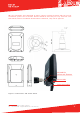
have xed coordinates relative to the sym-
bol on the front side of the anchor (Figure
4). The correction factors for determining
the precise location of the anchor are: 0
mm for the X-axis, 15mm for the Y-axis and
36 mm for the Z-axis.
Figure 4. Local coordinate system for the
anchors.