
User's Manual


Control and Functions
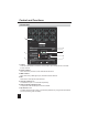
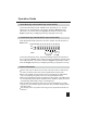
1. Front View
1. Output:
2. Power indicator:
3. DMX indicator:
4. Mic:
When this unit is powered on, this LED-indicator will be lit.
When there is any DMX signal input, this LED-indicator will be lit.
With a built-in microphone inside this hole.
There are 4 dual Edison sockets for channel output. Up to 5amps can be connected
to each channel.
3
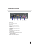
5. Channel indicators 1-4:
6. Audio sensitivity adjusting knob:
To indicate the input of 1-4 channels respectively.
To adjust the audio sensitivity level as user's desire.
7. Dip-switches 1-12:
To select desired function mode or set relevant parameters by using these dip-switches
(see the operation guide for details).
RS
ON
10
9876
5
4
3
21
111 2
1234
OUTPUT : 5A/CH , TOTAL 15A MAX.
CAUTION!
Warning : This unit must be grounded
N'ouvrez pas..risque de choc electrique
Risk of Electric Shock
DO NOT OPEN
Max
Min
142
3
AUDIO
SENSITIVITY
DMX
Indicator
Power
Indicator
ON
OFF
(1) (2) (3) (4) (5) (6) (7) (8) (9) (10)
Dipswitch#
Value
1
8
Program
Single( )
Or
Loop( )
On
Off
2
4
AUDIO MODE
(Dipswitch9=OFF, Dipswitch10=OFF):
AUTO MODE
(Dipswitch9=ON, Dipswitch10=OFF):
Dipswitch#
Value
11
2
4
8
Speed
Program
Single( )
Or
Loop( )
2
4
On
Off
(1) (2) (3) (4) (5) (6) (7) (8) (9) (10)
4 Channel Dimmer Pack
1 : Ground
2 : Data -
3 : Data +
Analog input: DC 0-10V
1. DC +15V 500mA
2. NC
3. Channel 1
4. Channel 2
5. Ground
6. Channel 3
7. Channel 4
8. NC
5
46
37
2
8
1
DMX Address Setting
111234 56 78 9
1
2
4
8
16
32
64
128
256
10 12
D/S
SLAVE MODE
(Dipswitch10=ON):
Dipswitch11:
Channel1- 2 ON(Dimmer) / OFF(Switch)
Dipswitch12:
Channel3- 4 ON(Dimmer) / OFF(Switch)
1
2
3
7
4
5
6