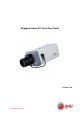
Megapixel Indoor IPC Quick Start Guide Version 3.0.0 eLineTechnology.
Welcome Thank you for purchasing our IP camera! This quick start guide is designed to be a reference tool for your system. Please keep this start guide well for future reference. 1.Electrical safety All installation and operation here should conform to your local electrical safety codes. The power shall conform to the requirement in the SELV (Safety Extra Low Voltage) and the Limited power source is rated 12V DC or 24V AC in the IEC60950-1.
Accessory Name IPC Unit C/CS adapter Quick Start Guide CD Amount ■ 1 ■ 1 ■ 1 ■ 1 ii eLineTechnology.
Table of Contents 1 2 Framework...................................................................................................................................1 1.1 Rear Panel.....................................................................................................................1 1.2 Side Panel .....................................................................................................................5 1.3 Front Panel ..........................................................
Appendix Toxic or Hazardous Materials or Elements ...............................................................21 iv eLineTechnology.
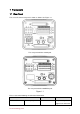
1 Framework 1.1 Rear Panel This series IP camera real panel is shown as below. See Figure 1-1. The rear panel with the network port The rear panel with the 100M fiber port Figure 1-1 Please refer to the following sheet for detail information. Interface Name VIDEO OUT Video output port Connector Function BNC Output analog video signal. Can connect to eLineTechnology.
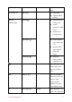
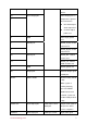
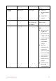
TV monitor to view video. AC 24V/ DC 12V Power port z Power port. z Input 12V DC or AC 24V STATUS z Red light Indication Light System boot upred light is on z System upgrades-red light flashes z System resetsred light flashes. z Green light Normal working status-green light is on. z Display record status:Recordgreen light flashes. z Yellow light Detect the wireless deviceyellow light is on. 3G Connect to 3G card. Please note it is for 3G series product only.
the external alarm device. NO Alarm output port Alarm output port. To output alarm signal to C the alarm device. z NO: Normal open alarm output end. z C: Alarm output public end. G GND Alarm input ground end. A RS485_A port, control RS485 port external PTZ B RS485_B port, control external PTZ RX RS232_RX,RS232 RS232 port receive end. TX RS232_TX,RS232 COM send out end. G GND RS232 ground end NA IR light port External IR light signal control port.
JACK port. from devices such as pick-up. LAN Network port Ethernet port z Connect to standard Ethernet cable. z Support PoE function. OPT 100M fiber port 155M single fiber Transmit 100M dual-direction SFP Ethernet data. fiber module SD SD card port Connect to SD card. Note z When you install the SD card, please make sure current card is not in write mode and then you can install it to the camera. z When you remove the SD card, please make sure current card is not in write mode.
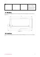
GND Please make sure the device is securely earthed to prevent the thunderstorm strike. 1.2 Side Panel Please refer to the following interface for side panel dimension information. The unit is mm. See Figure 1-2. Figure 1-2 1.3 Front Panel Please refer to the following interface for the front panel information. The unit is mm. See Figure 1-3. eLineTechnology.
Figure 1-3 eLineTechnology.
2 Installation 2.1 Lens Installation 2.1.1 Auto Aperture Lens Please follow the steps listed below for auto aperture lens installation. The interface is shown as in Figure 2-1 and Figure 2-2. z Remove the CCD protection cap of the device, and then line up the lens to the proper installation position. Turn clockwise until the lens is fixed firmly. z Insert the lens cable socket to the auto lens connector in the side panel. Figure 2-1 2.1.
Figure 2-2 2.1.3 Remove Lens Please follow the steps listed below to remove lens. The interface is shown as in Figure 2-3. z Turn the lens counter clockwise and then remove it from the camera. z Unplug the auto lens cable socket from the auto lens connector. If you are using the manual aperture lens, please skip to the following step. z If there is no lens, please put the CCD protection cap back to protect the CCD. Figure 2-3 2.2 SD Card 2.2.
Figure 2-4 Figure 2-5 2.2.2 Remove Please follow the steps listed below to remove SD card. The interface is shown as Figure 2-6. z Use the screwdriver to loosen the screw of SD card protection cap in the rear panel. Remove the cap from the camera. z Follow the SD card direction to remove the SD card. z Insert the SD card protection cap. z Use the screwdriver to fix the screw to secure the protection cap. Figure 2-6 2.3 3G Card 2.3.1 Installation The 3G card installation is the same with the SD card.
z z z z Use the screwdriver to loosen the 3G card protection cap screw in the side panel, and then remove the 3G card protection cap from the camera. Install the 3G card to the camera according to the proper installation position. Put the 3G card protection cap back. Use the screwdriver to fix the 3G card protection cap screw firmly to secure the 3G card protection cap. Figure 2-7 Figure 2-8 2.3.2 Remove Please follow the steps listed below to remove 3G card. The interface is shown as Figure 2-9.
2.4 3G/WIFI Antenna 2.4.1 Installation Line up the thread of the screw of the 3G/WIFI antenna to the thread of the rear panel. See Figure 2-10. Please turn according to the direction in the following figure until antenna is secure firmly. See Figure 2-11. Figure 2-10 Figure 2-11 After you fix the 3G/WIFI antenna to the WIFI port of the rear panel, you can adjust the antenna direction. See Figure 2-12. Figure 2-12 eLineTechnology.
2.4.2 Remove Use your hands to hold the 3G/WIFI thread end and then turn according to the following figure. See Figure 2-13. Now you can see the antenna is away from the thread. See Figure 2-14. Figure 2-13 Figure 2-14 Remove the 3G/WIFI antenna from the port of the rear panel. See Figure 2-15. Figure 2-15 2.5 I/O Port 2.5.1 Install and Remove Cable Install Cable eLineTechnology.
Please follow the steps listed below to install the cable. See Figure 2-16. Use the small slotted screwdriver to press the corresponding button of cable groove. Insert the cable into the groove and then release the screwdriver. Remove Cable Please follow the steps listed below to remove the cable. Use the small slotted screwdriver to press the corresponding button of cable groove. Remove the cable out of the groove and then release the screwdriver. Figure 2-16 2.5.
Please refer to the following figure for external IR light information. See Figure 2-19. IR synchronization input signal. When the external IR light is on, the signal cable from the board outputs the 3.3V/1mA. It outputs the 0V when the IR light is off. Figure 2-19 eLineTechnology.
3 Quick Configuration Tool 3.1 Overview Quick configuration tool can search current IP address, modify IP address. At the same time, you can use it to upgrade the device. Please note the tool only applies to the IP addresses in the same segment. 3.2 Operation Double click the “ConfigTools.exe” icon; you can see an interface is shown as in Figure 3-1. In the device list interface, you can view device IP address, port number, subnet mask, default gateway, MAC address and etc.
Select the “Open Device Web” item; you can go to the corresponding web login interface. See Figure 3-3. Figure 3-3 If you want to modify the device IP address without logging in the device web interface, you can go to the configuration tool main interface to set. In the configuration tool search interface (Figure 3-1), please select a device IP address and then double click it to open the login interface. Or you can select an IP address and then click the Login button to go to the login interface.
Figure 3-5 For detailed information and operation instruction of the quick configuration tool, please refer to the Quick Configuration Tool User’s Manual included in the resources CD. eLineTechnology.
4 Web Operation This series IPC product support the Web access and management via PC. Web includes several modules: monitor channel preview, PTZ control, system configuration, alarm and etc. 4.1 Network Connection Please follow the steps listed below for network connection. z Make sure the IPC has connected to the network properly. z Please set the IP address, subnet mask and gateway of the PC and the IPC respectively. IPC default IP address is 192.168.1.108. Subnet mask is 255.255.255.0. Gateway is 192.
Figure 4-2 If it is your first time to login in, system pops up warning information to ask you whether install control webrec.cab or not after you logged in for one minute. Please click OK button, system can automatically install the control. When system is upgrading, it can overwrite the previous Web too. If you can’t download the ActiveX file, please check whether you have installed the plug-in to disable the control download. Or you can lower the IE security level. See Figure 4-3.
Figure 4-4 Please refer to the Web Operation Manual included in the resource CD for detailed operation instruction. eLineTechnology.
Appendix Toxic or Hazardous Materials or Elements Component Name Toxic or Hazardous Materials or Elements Pb Hg Cd Cr VI PBB PBDE Circuit Board Component ○ ○ ○ ○ ○ ○ Device Construction Material ○ ○ ○ ○ ○ ○ Wire and Cable ○ ○ ○ ○ ○ ○ Power Adapter ○ ○ ○ ○ ○ ○ Packing Components ○ ○ ○ ○ ○ ○ Accessories ○ ○ ○ ○ ○ ○ O: Indicates that the concentration of the hazardous substance in all homogeneous materials in the parts is below the relevant threshold of the SJ/T