Infrared Mini High Speed Dome Camera USE/INSTALLATION SUPER SPEED DOME USER INSTRUCTION Copyright(c)2013(V3.
Special Declaration Before connecting and using this device, please read this manual carefully and properly preserved for reference in the future. Th i s m a n u a l m ay c o n t a i n s o m e i n a c c u r a t e p l a c e i n t e c h n o l o g y, o r s o m e printing error. The contents of this man u a l w i l l u p d a t e fro m t i m e t o t i m e , b u t without notice if there is any upgrades ; U p date contents will b e a d d e d i n n e w v e r s i o n m a n u a l .
CAUTION Careful Transport During transport, custody and installation should prevent damage to this product by weight, severe vibration and soak. Power Supply, Video Cable and Control Cable For power supply cable, video cable and control cable, please adopt shielded cable and independent wiring, can not mix with other cables. Clean When clean camera housing, please use dry soft cloth to wipe, If it is very dirty, please use neutral cleanser to wipe lightly.
CONTENTS Chapter 1 Product Overview .....................................................................................3 1.1 Product Features........................................................................................................3 1.2 Function Instruction ..................................................................................................4 1.3 Speed Dome Parameter .............................................................................................5 1.
Chapter 1 Product Overview 1.1 Product Feature Strong Intelligent Function • PELCO-D/P,Hikvision,Dahua protocol auto diagnosis. • 2400.4800,9600 baud rate auto diagnosis. Strong Horizontal and vertical Function making video image preview more comfortable. •Precision stepper motor subdivision technology, speed dome's lowest rotate speed reach 0.6 degree per second. Under high zoom situation, can move image more accurately and stablely.
Chapter 1 Product Overview 1.2 Function Instruction Address Code Setup Any operation commands has its own target speed dome camera address code,baud rate and control protocol, single camera only response the operation commands corresponded the same address code, baud rate and control protocol. This IR high speed dome camera 's baud rate, control protocol will be identified automatically by system.
Chapter 1 Product Overview Iris Control User can adjust the camera’s iris through control keyboard and manual adjust to get needed image brightness. Auto patrol Put some presets as a group in a certain sequence, it will run this patrol continuously when speed dome camera is in idle mode. Mode Scan Mode scan is through menu to save speed dome tracking route, it will run this mode scan continuously when speed dome camera is in idle mode. 1.
Chapter 1 Product Overview 1.4 Structure Dimension Speed Dome Dimension 135.9 135.9 Unit:mm Bracket Dimension Wall Mount Bracket 191.9 64.0 ∅6.5 96.0 113.7 81.5 Unit:mm Ceiling Mount Bracket ∅83.7 124.3 Dimension 199.0 322.5 218.0 ∅66.1 ∅3.
Chapter 2 Installation 2.1 Install Instruction Prepare before installation In order to prevent troubles, installation should be done by professional staff base on corresponding rules. Confirm all spare-parts are complete, ensure application of this speed dome camera and installation mode is suitable to requirement. All tests have been done before leaving factory, user can directly install and use it. 2.
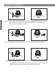
Chapter 2 Installation Installation Step 3- Please unscrew the two screws on the transparent DIP switch cover. Use screwdriver open the 2 screw which used to fix the transparent DIP switch cover as above picture. Step-4: Please refer to the third section of this chapter- Baud rate setup. Step-5: Install the transparent DIP switch cover. Please put the 2 holes of the transparent DIP switch cover focus to the two screw hole of the speed dome cover, then use screwdriver to install that 2 screws.
Chapter 2 Installation Step 7: Ceiling mount connect speed dome and bracket.Put the connection port of the speed dome into bracket hole and put the screw lock into corresponding threaded holes. Step 8: Fix the speed dome camera. Lead cable drawn out from the holder recess, then put the 4 installation hole of bracket of speed dome focus on the wall / ceiling's 4pcs expansion screw and tighten that 4pcs nut. Then seal the appeared groove via glass glue.
Chapter 2 Installation 2.3 Baud Rate And Terminal Resistor Setup Baud rate and corresponding DIP status as bellow: Baud Rate 2400bps 4800bps ON 1 9600bps ON 2 1 Automatic identify ON 2 1 ON 2 1 2 Installation RS485 control bus need all device which connect to it shall be in parallel mode, and each end of the system shall be connected to a 120 Ω resistor.
Chapter 2 Installation 4 5 OFF ON OFF OFF ON ON OFF OFF OFF OFF OFF OFF OFF OFF OFF OFF OFF ON ON OFF OFF OFF OFF OFF ON ON ON OFF OFF OFF OFF OFF 8 OFF OFF OFF OFF OFF OFF OFF 9 ON OFF OFF ON ON OFF OFF OFF OFF 10 OFF ON OFF ON OFF OFF OFF OFF 11 12 ON OFF ON OFF OFF ON ON ON OFF OFF OFF OFF OFF OFF OFF OFF --254 --OFF --- --ON --- ON ON --ON --ON --ON --ON 255 ON ON ON ON ON ON ON ON 2.
Chapter 2 Installation DC Connector DC12V RS485 Cable RS485A RS485B Video Cable BNC Connector Installation DC12V connection details: Port mark Port instruction Cable color/type Connection instruction Power line DC12V input port DC connector Connect to DC12V power supply RS485A RS485+ white Connect to RS485+ RS485B RS485- green Connect to RS485- Video line Video output port BNC connector Connect to monitor or other device 2.
Chapter 3 Basic Operation Because different system platform's specific operation method is not totally same, generally subject to manufacturer's manual, different situation has special requirements and operation method.Please contact distributor to obtain necessary information. Hereby only introduce control method when it connect universal keyboard controller. 3.
Chapter 3 Basic Operation 3.
Chapter 4 Menu Setup 4.
Chapter 4 Menu Setup This Chapter will introduce the OSD menu operation in detail. PTZ self-test when power up, it will display the following information on the monitor. PROTOCOL AUTO BAUD RATE AUTO HARD ADDR 1 SOFT ADDR 1 SOFT ADDR ENABLE OFF Setting Due to the PTZ operation is not complete the same based on different surveillance system, for the detail operation, please contact with distributors.Below is the general introduction of the basic operation of the keyboard control to the OSD menu.
Chapter 4 Menu Setup Cancel Setting Back to the last menu: press【Close】button, back to the last menu, it is valid under the tips. Exit Menu Up/down move the joystick to make the cursor point to the "Exit" option, then press【OPEN】button, Exit the OSD Menu. After the PTZ powered up and work normally, SHOT 95, enter main menu, the monitor displayed as below diagram 4.1. MAIN MENU SYSTEM INFORMATION DISPLAY SETTING SYSTEM SETTING IR LED SETTING → → → → RESTART CAMERA RESET EXIT Diagram 4.
Chapter 4 Menu Setup 4.3 System Information Menu To check the basic information of the PTZ. SYSTEM INFORMATION PROTOCOL AUTO BAUD RATE AUTO HARD ADDR 1 Setting SOFT ADDR 1 SOFT ADDR ENABLE OFF TEMPERATURE 30 VERSION 08130801 Diagram4.3 System Information Menu EXIT The explanation of each option in System Information : Display the serial port of communication protocols of the PTZ. : Display the communicate speed of the PTZ.
Chapter 4 Menu Setup The explanation of each option in Display setting menu : The screen will display the time when operate the PTZ. : Will display the time when operate the PTZ. : Set the Alarm 4.5 System Setting menu SYSTEM SETTING CAMERA MOVEMENT CONTROL PRESET PATROL TRACK PATTERN ALARM REMOVE EXIT Setting → → → → → → → Diagram4.5 System Setting Menu 4.5.1 Camera : To set the parameters of the zoom module, select enter.
Chapter 4 Menu Setup 4.5.2 Movement Control : To set the Movement parameter of the PTZ, and enter. MOVEMENT CONTROL AUTO FLIP ON PROPORTION PAN OFF PARK TIME NO PARK ACTION NO Setting POWER ACTION NO CONTROL SPEED HIGH AB SCAN SETTING AB SCAN PATH I-ARC AB SCAN SPEED HIGH LIMIT STOP OFF LIMIT SETTING THE NORTH SETTING EXIT Diagram 4.5.
Chapter 4 Menu Setup 4.5.3 Preset : execute the operation of the Preset, enter. PRESET NUMBER 1 LABEL DEFAULT EDIT REMOVE Diagram 4.5.3 Preset The explanation of each option in Preset menu. : Select the No. Of the preset, 1-220 is valid.
Chapter 4 Menu Setup 4.5.5 Pattern : Execute the operation of the Pattern, enter. PATTERN NUMBER EDIT PREVIEW REMOVE EXIT 1 Setting Diagram 4.5.5 Pattern The explanation of each option in Pattern Scan menu. : Select the No. Of the Pattern Scan, 1-4 is valid. : Edit and record the path of the selected Pattern Scan. : Preview the selected Pattern Scan. : Remove the selected Pattern Scan. 4.5.
Chapter 4 Menu Setup 4.5.7 Remove : Remove the Preset, Patrol track, Pattern Scan information. REMOVE PRESET 1 PATROL TRACK PATTERN EXIT Diagram 4.5.7 Remove Setting The explanation of each option in Remove menu. : Remove all the Presets. : Remove all the Patrol Tracks. : Remove all Patterns. 4.6.
Chapter 5 Appendix 5.
Chapter 5 Appendix 5.3 Lightning and Surge protection Outdoor speed dome camera must consider thunder-proof and surge immunity. On the premise of guaranteeing electrical safety,we can take following lightning protection measures: Atleast keep 50m distance between signal transmission line and high voltage equipment or high voltage cable. Outdoor wiring under the eaves.
Chapter 5 Appendix 5.4 RS485 Bus Wiring 1. RS485 bus basic characteristic RS485 industry bus is characteristic impedance 120Ω half-duplex communication bus according to RS485 industry bus standard. Appendix 2. RS485 bus transmission distance When use 0.511mm (24AWG) screen twisted pair cable as communication cable.
B