In-Ceiling Electric Motorized Front Projection Screen Evanesce Tension Series User’s Guide 1 Rev.122411-AS www.elitescreens.com info@elitescreens.
Important Safety & Warning Precautions Make sure to read this user’s guide and follow the procedure below. Caution: The screen’s Black Top Drop is already set to its maximum drop distance. There is NO extra Black Top Drop in the roller. Please be aware of this as it will void your warranty with Elite Screens. Unapproved changes or modifications (except for cutting the power cord for hardwire installations) to this unit are prohibited and will void your warranty.
Installation Warning Due to various installation environments, the instructions provided in this user’s guide are for reference only. Please consult a professional installation company for further installation and safety advice. The installer must insure that proper mounting hardware is used to provide adequate strength suitable for the installation. Elite Screens is not liable for any faulty installations.
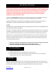
Accessories for Evanesce Tension Series Please make sure all accessories listed below are included before proceeding. A. IR Remote B. RF Remote C. 3 Way Wall Switch D. IR Eye Receiver G. AAA Batteries Red+ E. 12V Trigger GreenF. In-Wall RJ-45 Module H. Bubble Level 4 Rev.122411-AS www.elitescreens.com info@elitescreens.
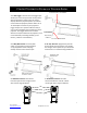
Control System for Evanesce Tension Series RJ-45 INPUT FOR 5-12V TRIGGER 1. 5-12V Trigger: The built-in 5-12V trigger input allows your screen to synchronize its drop & rise with the projector’s power cycle. The screen deploys when the projector powers up and will retract when the projector powers down. The 512 volt adaptor connects to your projector’s trigger output via a separate cable that may or may not be provided by the manufacturer of the projector.
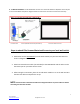
. In-Wall RJ-45 Module: The RJ-45 Module connects to a local wall switch for UP/Down control of your screen. Please follow the picture diagram below for instructions on how to connect the accessory. Elite Screens In-Wall Switch Module ( ZIW-Module ) Ethernet (RJ45) network cable (not included) Local Wall Switch In-Wall UP/DOWN Switch Module (ZIW-Module) Elite Electric Motorized Screen Steps to attach Elite Screens Motorized Screen to your local wall switch 1.
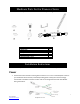
Hardware Parts List for Evanesce Series Please make sure all parts listed below are included before proceeding with the installation. G Hardware Parts List A. Case Rail Nut B. Hex Screw C. Hanging Bracket D. Suspension Bar E. Washer F. Hex Nut QTY 4-6 4-6 2-3 4 8-10 4-6 G. Suspension Bar J- Hook 4 Installation Instructions Please consult a professional installer. Elite Screens is not liable for faulty installations. Power 1.
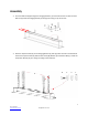
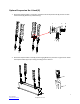
Assembly 2. Insert the Hex Screw (B) through the Hanging Bracket’s (C) screw hole and secure with the Case Rail Nut (A). Slide the Hanging Bracket (C) through the railing on top of the case. 3. Place the Suspension Bar (D) on the Hanging Bracket (C) and align with the hole as shown below. Secure the Suspension Bar (D) with the Hex Screw (B), Washer (E) and the Hex Nut (F). Install the Suspension Bars (D) to your ceiling according to their distance. B D E E F 8 Rev.122411-AS www.elitescreens.
Optional Suspension Bar J-Hook (G) 1. Attach the Suspension Bar J- Hook (G) to the bottom of the Suspension Bar (D) and secure with the Hex Screw (B), Washer (E) and Hex Nut (F). F E E B 2. Attach the Suspension Bar J-Hook (G) to the Hanging Bracket (C) as shown in figure below. Install the Suspension Bars (D) to your ceiling according to their distance. G C 9 Rev.122411-AS www.elitescreens.com info@elitescreens.
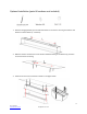
Optional Installation (parts & hardware not included) 1. Place the Hanging Bracket (C) in the desired location on the screen’s housing and measure the distance as shown below. (L = Distance) 2. Mark the location of where the screen will be installed according to the distance (L) and then secure the bolt to the ceiling. 3. Install the screen to the screw bolt as shown in the figure below. 10 Rev.122411-AS www.elitescreens.com info@elitescreens.
Evanesce Tension Series Dimension Table *Measurement dimensions are for reference only and subject to change without notice. Note: Data Error may be ±1" 11 Rev.122411-AS www.elitescreens.com info@elitescreens.
Warranty Policy • • • • • • • • Two (2) Year parts and labor warranty from defects in workmanship from purchase date as follows (except for refurbished units as specified below). Three (3) Year parts and labor warranty from defects in workmanship for GEMR (Government, Educational, Military, & Religious) purchases of new product only. Refurbished Units carry a 90-DAY parts and labor warranty. Each party will be responsible for one way shipping during the warranty period.
Contact Information US & Canada Tech Support & Warranty Claim Please contact us at service@elitescreens.com or call +1 877-511-1211 #3 or fax +1-562-926-8433 Europe Tech Support & Warranty Claim Please contact us at service@elitescreens.eu or call +49-(0) 40-30392958 Asia Tech Support & Warranty Claim Please contact us at service@elitescreens.com.cn or call +86-(0) 755-8461-7989 Taiwan Tech Support & Warranty Claim Please contact us at service@elitescreens.com.