Preface Copyright This publication, including all photographs, illustrations and software, is protected under international copyright laws, with all rights reserved. Neither this manual, nor any of the material contained herein, may be reproduced without written consent of the author. Version 1.0 Disclaimer The information in this document is subject to change without notice.
ii Declaration of Conformity This device complies with part 15 of the FCC rules. Operation is subject to the following conditions: • • This device may not cause harmful interference, and This device must accept any interference received, including interference that may cause undesired operation Canadian Department of Communications This class B digital apparatus meets all requirements of the Canadian Interferencecausing Equipment Regulations.
iii TABLE OF CONTENTS Preface i Chapter 1 1 Introducing the Motherboard 1 Introduction......................................................................................1 Feature...............................................................................................2 Motherboard Components.............................................................4 Chapter 2 7 Installing the Motherboard 7 Safety Precautions...........................................................................
iv Frequency/Voltage Control................................................41 Load Default Settings........................................................42 Supervisor Password........................................................42 User Password..................................................................43 Save & Exit Setup..............................................................43 Exit Without Saving............................................................43 Updating the BIOS...........
1 Chapter 1 Introducing the Motherboard Introduction Thank you for choosing 945GSED-I motherboard of great performance and with enhanced function. This motherboard has onboard Intel ® AtomTM Processor N270 with a Mini-ITX form factor of 170 x 170 mm. The motherboard incorporates the 945GSE Northbridge (NB) and ICH7-M Southbridge (SB) chipsets. The Northbridge supports a Front Side Bus (FSB) frequency of 533 MHz using a scalable FSB Vcc_CPU.
2 Feature Processor This motherboard uses onboard Intel ® AtomTM Processor N270 that carries the following features: • • Onboard Intel® AtomTM Processor N270, on-die 512-kB, 8-way L2 cache Supports a system bus (FSB) of 533 MHz Chipset The 945GSE Northbridge (NB) and ICH7-M Southbridge (SB) chipsets are based on an innovative and scalable architecture with proven reliability and performance.
3 Expansion Options The motherboard comes with the following expansion options: • • • One 32-bit PCI v2.3 compliant slot One IDE connector that supports two IDE devices Two 7-pin SATA connectors The motherboard supports UDMA bus mastering with transfer rates of 100/66/33 Mb/s.
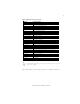
4 Motherboard Components Introducing the Motherboard
5 Table of Motherboard Components LABEL COMPONENTS 1. DIMM1 240-pin DDR2 SDRAM slots 2. SYS_FAN System cooling fan connector 3. J1 Chassis intrusion detect header 4. LPT2 Onboard parallel port header 5. JP3 Select +5V/ +12V/RI/DCD jumper 6. ATX_POWER1 Standard 20-pin ATX power connector 7. J6~7 Select COM4 level jumper 8. J4~5 Select COM3 level jumper 9. COM3/4/5/6/8 Serial port connectors 10. JP2/6 Select +5V/ +12V/DCD jumper 11. CLR_CMOS1 Clear CMOS jumper 12. IDE1 Primary IDE connector 13.
6 Memo Introducing the Motherboard
7 Chapter 2 Installing the Motherboard Safety Precautions • • • • • Follow these safety precautions when installing the motherboard Wear a grounding strap attached to a grounded device to avoid damage from static electricity Discharge static electricity by touching the metal case of a safely grounded object before working on the motherboard Leave components in the static-proof bags they came in Hold all circuit boards by the edges.
8 Do not over-tighten the screws as this can stress the motherboard. Checking Jumper Settings This section explains how to set jumpers for correct configuration of the motherboard. Setting Jumpers Use the motherboard jumpers to set system configuration options. Jumpers with more than one pin are numbered. When setting the jumpers, ensure that the jumper caps are placed on the correct pins. The illustrations show a 2-pin jumper. When the jumper cap is placed on both pins, the jumper is SHORT.
9 Checking Jumper Settings The following illustration shows the location of the motherboard jumpers. Pin 1 is labeled.
10 Jumper Settings Jumper Type Description Setting (default) 1-2: NORMAL CLR_CMOS1 2-3: CLEAR CMOS 3-pin CLEAR CMOS Before clearing the CMOS, make sure to turn the system off.
11 Jumper Type Description Setting (default) 1-3: COM2 pin9=+5V 3-5: COM2 pin9=+12V JP4 10 9 Select +5V/ 7-9: COM2 pin9=R1 10-pin +12V/RI/DCD 2-4: COM2 pin1=+5V 4-6: COM2 pin1=+12V 2 1 JP4 8-10: COM2 pin1=DCD 1-3: COM7 pin9=+5V 3-5: COM7 pin9=+12V JP5 10-pin 7-9: COM7 pin9=R1 Select +5V/ +12V/RI/DCD 2-4: COM7 pin1=+5V 4-6: COM7 pin1=+12V 10 9 2 1 JP5 8-10: COM7 pin1=DCD 1-3: COM8 pin9=+5V 3-5: COM8 pin9=+12V JP6 10-pin 10 9 7-9: COM8 pin9=RI Select +5V/ +12V/RI/DCD 2-4: COM8 pin1=+5V
12 Installing Hardware Installing Memory Modules This motherboard accommodates one memory module. It can support one 240-pin DDR2 533/400. The total memory capacity is 2 GB. DDR2 SDRAM memory module table Memory module Memory Bus DDR2 533 DDR2 400 266 MHz 200 MHz Do not remove any memory module from its antistatic packaging until you are ready to install it on the motherboard. Handle the modules only by their edges. Do not touch the components or metal parts.
13 Table A: DDR2 (memory module) QVL (Qualified Vendor List) The following DDR2 800/667/533 memory modules have been tested and qualified for use with this motherboard. Type DDR2 533 Size Vendor 512 MB Samsung PC2-4200U-4444-10-B1 A-data Kingmax Apacer Micron PSC Ramxel Samsung Samsung Aeneon Apacer Hexon Hynix Kingston LeadMax 533/A-DATA/Vitesta/1GB/DS KLBD48F-A8KE4 78.91G92.9K5 MT4HTF6464AY-667E1 AL6E8E63J-6E1 RML1520M38D6F-667 PC2-5300U-555-12-D3 1GB UNB PC2-5300 CL5 78.01G9O.
14 Type Size Vendor Module Name KVR800D2N5/512 1.8V 9905315Kingston 512 MB 019.A02LF A-DATA M2GVD6G3I41P0U1E5E AU01GE800C5KBGC Apacer 78.01GAO.9K5 78.01GA0.9L5 APOGEE AU1G082-800P000 Geil Geil Millenary Hynix HYMP112U64CP8-S6 AB Infinity 04701G16CZ5U2G KingMax KLDD48F-B8KU5 NGES Kingston KVR800D2N5/1G 1.8V 99053161 GB 054.
15 Expansion Slots Installing Add-on Cards The slots on this motherboard are designed to hold expansion cards and connect them to the system bus. Expansion slots are a means of adding or enhancing the motherboard’s features and capabilities. With these efficient facilities, you can increase the motherboard’s capabilities by adding hardware that performs tasks that are not part of the basic system. PCI1 Slot This motherboard is equipped with one standard PCI slot.
16 Follow these instructions to install an add-on card: 1 2 3 Remove a blanking plate from the system case corresponding to the slot you are going to use. Install the edge connector of the add-on card into the expansion slot. Ensure that the edge connector is correctly seated in the slot. Secure the metal bracket of the card to the system case with a screw. 1.
17 Connecting Optional Devices Refer to the following for information on connecting the motherboard’s optional devices: F_AUDIO1: Front Panel Audio header This header allows the user to install auxiliary front-oriented microphone and lineout ports for easier access.
18 F_USB1: Front Panel USB header The motherboard has four USB ports installed on the rear edge I/O port array. Additionally, some computer cases have USB ports at the front of the case. If you have this kind of case, use auxiliary USB connector to connect the front-mounted ports to the motherboard.
19 COM2~8: Onboard serial port connectors Connect a serial port extension bracket to this header to add a second serial port to your system.
20 LVDS1~2: LVDS connectors This motherboard supports two LVDS headers that are used to connect the LCD (Liquid Crystal Display). LVDS (Low Voltage Differencial Signaling) provides robust signaling for high-speed data transmission between chassis, boards and peripherals using standard ribbon cables and IDC connectors.
21 Installing a Hard Disk Drive/CD-ROM/SATA Hard Drive This section describes how to install IDE devices such as a hard disk drive and a CDROM drive. About IDE Devices Your motherboard has one IDE channel interface. An IDE ribbon cable supporting two IDE devices is bundled with the motherboard. You must orient the cable connector so that the pin1 (color) edge of the cable corresponds to the pin 1 of the I/O port connector.
22 Refer to the illustration below for proper installation: 1 2 3 Attach either cable end to the connector on the motherboard. Attach the other cable end to the SATA hard drive. Attach the SATA power cable to the SATA hard drive and connect the other end to the power supply. The SATA on this motherboard supports the “Hot-Plug” function.
23 Connecting I/O Devices The backplane of the motherboard has the following I/O ports: PS2 Mouse Use the upper PS/2 port to connect a PS/2 pointing device. PS2 Keyboard Use the lower PS/2 port to connect a PS/2 keyboard. Parallel Port (LPT1) Use LPT1 to connect printers or other parallel communications devices. Serial Port (COM1) Use the COM1 port to connect serial devices such as mouse or fax/modems. VGA1 Port Connect your monitor to the VGA1 port.
24 Connecting Case Components After you have installed the motherboard into a case, you can begin connecting the motherboard components. Refer to the following: 1 Connect the system cooling fan connector to SYS_FAN. 2 Connect the case switches and indicator LEDs to the PANEL1. 3 Connect the standard power supply connector to ATX_POWER1. Connecting 20-pin power cable The power 20-pin connector allows you to connect to ATX v2.x power supply.
25 SYS_FAN: FAN Power Connector Pin 1 2 3 Signal Name Function System Ground Power +12V Sensor GND +12V Sense ATX_POWER1: ATX 20-pin Power Connector Pin 1 2 3 4 5 6 7 8 9 10 Signal Name Pin Signal Name +12V +5VSB 11 12 13 14 15 16 17 18 19 +12V 20 +5V +3.3V +3.3V GND +5V GND +5V GND Power Good -12V GND Power On GND GND GND N.C.
26 Front Panel Header The front panel header (PANEL1) provides a standard set of switch and LED headers commonly found on ATX or Micro ATX cases.
27 Chapter 3 Using BIOS About the Setup Utility The computer uses the latest “American Megatrends Inc.” BIOS with support for Windows Plug and Play. The CMOS chip on the motherboard contains the ROM setup instructions for configuring the motherboard BIOS. The BIOS (Basic Input and Output System) Setup Utility displays the system’s configuration status and provides you with options to set system parameters.
28 Press the delete key to access the BIOS Setup Utility. CMOS Setup Utility -- Copyright (C) 1985-2008, American Megatrends, Inc.
29 Using BIOS When you start the Setup Utility, the main menu appears. The main menu of the Setup Utility displays a list of the options that are available. A highlight indicates which option is currently selected. Use the cursor arrow keys to move the highlight to other options. When an option is highlighted, execute the option by pressing . Some options lead to pop-up dialog boxes that prompt you to verify that you wish to execute that option.
30 For the purpose of better product maintenance, we reserve the right to change the BIOS items presented in the manual. The BIOS setup screens shown in this chapter are for reference only. Please visit our website for updated manual. Standard CMOS Setup This option displays basic information about your system. CMOS Setup Utility -- Copyright (C) 1985-2005, American Megatrends, Inc.
31 f Primary IDE Master/Primary IDE Slave/SATA1~2 Your computer has one IDE channel and each channel can be installed with one or two devices (Master and Slave). In addition, this motherboard supports two SATA channels and each channel allows one SATA device to be installed. Use these items to configure each device on the SATA channel. CMOS SETUP UTILITY – Copyright (C) 1985-2005, American Megatrends, Inc.
32 IDE BusMaster (Enabled) This item enables or disables the DMA under DOS mode. We recommend you to leave this item at the default value. Press to return to the main menu setting page. Advanced Setup This page sets up more advanced information about your system. Handle this page with caution. Any changes can affect the operation of your computer. CMOS Setup Utility - Copyright (C) 1985-2005, American Megatrends, Inc.
33 1st/2nd/3rd Boot Device (Hard Drive/CD/DVD/Removable Dev.) Use this item to determine the device order the computer used to look for an operating system to load at start-up time. The devices showed here will be different depending on the exact devices installed on your motherboard. fHard Disk Drives (Press Enter) Scroll to this item and press to view the following screen: CMOS Setup Utility - Copyright (C) 1985-2005, American Megatrends, Inc.
34 Boot Other Device (Yes) When enabled, the system searches all other possible locations for an operating system if it fails to find one in the devices specified under the First, Second and Third boot devices. Case Open Warning (Yes) This item enables or disables the warning if the case is opened up, and the itembelow indicates the current status of the case. Chassis Opened (No) This item indicates whether the case has been opened. Press to return to the main menu setting page.
35 Advanced Chipset Setup This page sets up more advanced information about your system. Handle this page with caution. Any changes can affect the operation of your computer. CMOS Setup Utility - Copyright (C) 1985-2005, American Megatrends, Inc.
36 Integrated Peripherals This page sets up some parameters for peripheral devices connected to the system. CMOS Setup Utility - Copyright (C) 1985-2005, American Megatrends, Inc.
37 Onboard 10/100M Boot ROM (Disabled) Use this item to enable or disable the boot function using the onboard 10/100M LAN Boot ROM. Onboard GbE LAN (Enabled) Use this item to enable or disable the OnBoard GbE LAN function. Onboard GbE Boot ROM (Disabled) Use this item to enable or disable the boot function using the onboard GbE LAN Boot ROM. USB Functions (Enabled) Use this item to enable or disable the USB function.
38 ACPI Suspend Type (S3 (STR)) Use this item to define how your system suspends. In the default, S3, the suspend mode is a suspend to RAM, i.e, the system shuts down with the exception of a refresh current to the system memory. PWRON After PWR-Fail (Power Off) This item enables your computer to automatically restart or return to its operating status. Power On by Ring (Disabled) The system can be turned off with a software command.
39 PCI / PnP Setup This page sets up some parameters for devices installed on the PCI bus and those utilizing the system plug and play capability. CMOS Setup Utility - Copyright (C) 1985-2005, American Megatrends, Inc. PCI / PnP Setup Init Display First Help Item OnBoard Select which graphics controller to use as the primary boot device.
40 Shutdown Temperature (Disabled) Enable you to set the maximum temperature the system can reach before powering down. Warning Temperature (Disabled) This item enables or disables the warning temperature. System Component Characteristics These items display the monitoring of the overall inboard hardware health events, such as System & CPU temperature, CPU & DIMM voltage, CPU & system fan speed,...etc.
41 Frequency/Voltage Control This page enables you to set the clock speed and system bus for your system. The clock speed and system bus are determined by the kind of processor you have installed in your system. CMOS Setup Utility - Copyright (C) 1985-2005, American Megatrends, Inc.
42 Load Default Settings This option opens a dialog box that lets you install stability-oriented defaults for all appropriate items in the Setup Utility. Select and then press to install the defaults. Select and then press to not install the defaults. Supervisor Password This page helps you install or change a password. CMOS Setup Utility - Copyright (C) 1985-2005, American Megatrends, Inc.
43 User Password This page helps you install or change a password. CMOS Setup Utility - Copyright (C) 1985-2005, American Megatrends, Inc. User Password User Password : Not Installed Change User Password mnkl : Move Enter : Select F1:General Help Help Item Press Enter +/-: Value Install or Change the password. F10: Save and Exit ESC: Exit F9: Optimized Defaults User Password (Not Installed) This item indicates whether a user password has been set.
44 Updating the BIOS You can download and install updated BIOS for this motherboard from the manufacturer’s Web site. New BIOS provides support for new peripherals, improvements in performance, or fixes for known bugs. Install new BIOS as follows: 1 If your motherboard has a BIOS protection jumper, change the setting to allow BIOS flashing. 2 If your motherboard has an item called Firmware Write Protect in Advanced BIOS features, disable it. (Firmware Write Protect prevents BIOS from being overwritten.
45 Chapter 4 Using the Motherboard Software About the Software CD-ROM The support software CD-ROM that is included in the motherboard package contains all the drivers and utility programs needed to properly run the bundled products. Below you can find a brief description of each software program, and the location for your motherboard version. More information on some programs is available in a README file, located in the same directory as the software.
46 Setup Tab Setup Click the Setup button to run the software installation program. Select from the menu which software you want to install. Browse CD The Browse CD button is the standard Windows command that allows you to open Windows Explorer and show the contents of the support CD. Before installing the software from Windows Explorer, look for a file named README.TXT, INSTALL.TXT or something similar. This file may contain important information to help you install the software correctly.
47 2. Click Next. The following screen appears: 3. Check the box next to the items you want to install. The default options are recommended. 4. Click Next run the Installation Wizard. An item installation screen appears: 5. Follow the instructions on the screen to install the items. 1. Drivers and software are automatically installed in sequence. Follow the onscreen instructions, confirm commands and allow the computer to restart a few times to complete the installation. 2.
48 Method 1. Run Reboot Setup Windows Vista will block startup programs by default when installing drivers after the system restart. You must select taskbar icon Run Blocked Program and run Reboot Setup to install the next driver, until you finish all drivers installation. Method 2. Disable UAC (User Account Control) * For administrator account only. Standard user account can only use Method 1.
49 2. Select Classic View. 3. Set User Account. 4. Select Turn User Account Control on or off and press Continue.
50 5. Disable User Account Control (UAC) to help protect your computer item and press OK, then press Restart Now. Then you can restart your computer and continue to install drivers without running blocked programs. Manual Installation Insert the CD in the CD-ROM drive and locate the PATH.DOC file in the root directory. This file contains the information needed to locate the drivers for your motherboard.