Preface Copyright This publication, including all photographs, illustrations and software, is protected under international copyright laws, with all rights reserved. Neither this manual, nor any of the material contained herein, may be reproduced without written consent of the author. Version 1.0 Disclaimer The information in this document is subject to change without notice.
Declaration of Conformity This device complies with part 15 of the FCC rules. Operation is subject to the following conditions: • This device may not cause harmful interference. • This device must accept any interference received, including interference that may cause undesired operation.
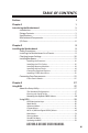
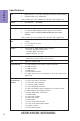
TABLE OF CONTENTS Preface i Chapter 1 1 Introducing the Motherboard 1 Introduction...........................................................................................1 Pakage Contents..................................................................................1 Specifications......................................................................................2 Motherboard Components................................................................4 I/O Ports...................................
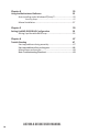
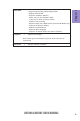
Chapter 4 55 Using the Motherboard Software 55 Auto-installing under Windows XP/Vista/7....................................55 Running Setup........................................................................55 Manual Installation..........................................................................57 Chapter 5 59 Setting Up AMD SB950 RAID Configuration 59 Setting Up a Bootable RAID Array..................................................
Introduction Chapter 1 Chapter 1 Introducing the Motherboard Thank you for choosing the A970M-A DELUXE motherboard. This motherboard is a high performance, enhanced function motherboard that supports socket for AMD PhenomTM and later desktop processors (socket AM3+) for high-end business or personal desktop markets. The motherboard is based on AMD 970 Northbridge (NB) and SB950 Southbridge (SB) chipsets. The memory controller supports DDR3 memory DIMM frequencies of 2133(OC)/1866/1600/1333.
Chapter 1 Specifications CPU • • AMD PhenomTM and later desktop processors (socket AM3+) Supports CPU up to 140W TDP Note: Please go to ECS website for the latest CPU support list. Chipset Extra Chipset Memory • NB: AMD 970 SB: SB950 • ASM1042 supports two USB 3.0 ports at the rear panel • • • Dual-channel DDR3 memory architecture 4 x 240-pin DDR3 DIMM sockets support up to 64 GB Supports DDR3 2133(OC)/1866/1600/1333 MHz DDR3 SDRAM Note: Please go to ECS website for the latest CPU support list.
• AMI BIOS with 32Mb SPI Flash ROM - Supports Plug and Play, S1/STR (S3)/STD (S4) - Supports ACPI & DMI - Supports Hardware Monitor - Audio, LAN, can be disabled in BIOS - F7 hot key for boot up devices option - Supports Over-Clocking - Supports PaUp clear CMOS Hotkey (Has PS2 KB Model only) - Supports Dual/Triple Display - Supports GUI UEFI BIOS II - Supports Multi-language - Supports AC’97/HD Audio auto detect (default) AP Support • Supports EZ Charger Chapter 1 System BIOS Note: Please go to ECS w
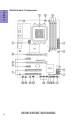
Chapter 1 4 Motherboard Components A970M-A DELUXE USER MANUAL
LABEL 1. CPU Socket 2. CPU_FAN 3. DDR3_1~4 4. ATX_POWER 5. PWR_FAN 6. SATA1~5 7. CLR_CMOS 8. F_PANEL 9. TPM 10. CASE 11. SPK 12. F_USB1~3 13. COM 14. SYS_FAN 15. SPDIFO 16. F_AUDIO 17. PCI1~2 18. PCIE1~2 19. PCIEX16_T 20. PCIEX16 21.
Chapter 1 I/O Ports 1. PS/2 Keyboard and PS/2 Mouse combo connector Use the PS/2 port to connect a PS/2 mouse or a PS2 keyboard. 2. USB 2.0 Ports Use the USB 2.0 ports to connect USB 2.0 devices. 3. USB 3.0 Ports Use the USB 3.0 ports to connect USB 3.0 devices. 4. LAN Port Connect an RJ-45 jack to the LAN port to connect your computer to the Network. LAN LED Activity LED Link LED Status Description OFF Orange blinking OFF Green No data Active No link Link Link LED LAN Port 5.
7. eSATA 6Gb/s Ports Use this port to connect to external SATA boxes or Serial ATA port multipliers. A970M-A DELUXE USER MANUAL Chapter 1 6. Optical SPIDF Output This jack connects to external optical digital audio output devices.
Chapter 1 8 Memo A970M-A DELUXE USER MANUAL
Chapter 2 Installing the Motherboard Follow these safety precautions when installing the motherboard: • • • • Wear a grounding strap attached to a grounded device to avoid damage from static electricity. Discharge static electricity by touching the metal case of a safely grounded object before working on the motherboard. Leave components in the static-proof bags.
2-3. Checking Jumper Settings The following illustration shows the location of the motherboard jumpers. Pin 1 is labeled.
2-4. Installing Hardware • • • • This motherboard has an AM3+ socket. When choosing a processor, consider the performance requirements of the system. Performance is based on the processor design, the clock speed and system bus frequency of the processor, and the quantity of internal cache memory and external cache memory. You may be able to change the settings in the system Setup Utility. We strongly recommend you do not over-clock processor or other components to run faster than their rated speed.
2-4-2. Installing the CPU Cooler • • • Chapter 2 • Install the cooling fan in a well-lit work area so that you can clearly see the motherboard and processor socket. Avoid using cooling fans with sharp edges in case the fan casing and the clips cause serious damage to the motherboard or its components. To achieve better airflow rates and heat dissipation, we suggest that you use a high quality fan with 3800 rpm at least.
• • • • This motherboard accommodates four memory modules. It can support four 240-pin DDR3 2133(OC)/1866/1600/1333. Do not remove any memory module from its antistatic packaging until you are ready to install it on the motherboard. Handle the modules only by their edges. Do not touch the components or metal parts. Always wear a grounding strap when you handle the modules. You must install at least one module in any of the four slots. Total memory capacity is 64 GB.
2-4-4. Installing Add-on Cards The slots on this motherboard are designed to hold expansion cards and connect them to the system bus. Expansion slots are a means of adding or enhancing the motherboard’s features and capabilities. With these efficient facilities, you can increase the motherboard’s capabilities by adding hardware that performs tasks that are not part of the basic system.
1 Remove a blanking plate from the system case corresponding to the slot you are going to use. 2 Install the edge connector of the add-on card into the expansion slot. Ensure that the edge connector is correctly seated in the slot. 3 Secure the metal bracket of the card to the system case with a screw. 1. For some add-on cards, for example graphics adapters and network adapters, you have to install drivers and software before you can begin using the add-on card.
2-4-5. Connecting Optional Devices Refer to the following for information on connecting the motherboard’s optional devices: Chapter 2 No. Components No. 1 SATA1~5 5 Components COM 2 TPM 6 SPDIFO 3 CASE 7 F_AUDIO 4 F_USB1~3 —— —— 1. SATA1~5: Serial ATA III connectors SATA1~5 connectors are used to support the new Serial ATA device for the highest data transfer rates (6.0 Gb/s), simpler disk drive cabling and easier PC assembly.
2. TPM: Trusted Platform Module header Chapter 2 Trusted platform module (TPM) is a published specification detailing a micro controller that can store secured information, and implementations of that specification. 3. CASE: Chassis Intrusion Detect Header This detects if the chassis cover has been removed. This function needs a chassis equipped with intrusion detection switch and needs to be enabled in BIOS.
4. F_USB1~3: Front Panel USB 2.0 headers The motherboard has three USB 2.0 headers supporting six USB 2.0 ports. Additionally, some computer cases have USB 2.0 ports at the front of the case. If you have this kind of case, use auxiliary USB 2.0 connector to connect the front-mounted ports to the motherboard. Chapter 2 F_USB1 supports EZ Charger technology, provides 3 times current than general USB 2.0 port in off mode for USB devices.
6. SPDIFO: SPDIF out header Chapter 2 This is an optional header that provides an SPDIFO (Sony/Philips Digital Interface) output to digital multimedia device through optical fiber or coaxial connector. 7. F_AUDIO: Front Panel Audio Header The front panel audio header allows the user to install auxiliary front-oriented microphone and line-out ports for easier access. This header supports HD audio by default.
AC’ 97 Audio Configuration: To enable the front panel audio connector to support AC97 Audio mode. If you use AC’ 97 Front Panel, please tick off the option of “ Disabled Front Panel Detect ”. If you use HD Audio Front Panel, please don’ t tick off “Disabled Front Panel Detect ” . Chapter 2 * For reference only If you use AC’ 97 Front Panel, please don’ t tick off “Using Front Jack Detect ”. If you use HD Audio Front Panel, please tick off the option of “Using Front Jack Detect ”.
2-4-6. Installing a SATA Hard Drive This section describes how to install a SATA Hard Drive. Your motherboard features five SATA connectors supporting a total of five drives. SATA refers to Serial ATA (Advanced Technology Attachment) is the standard interface for the IDE hard drives which are currently used in most PCs. These connectors are well designed and will only fit in one orientation. Locate the SATA connectors on the motherboard and follow the illustration below to install the SATA hard drives.
2-4-7. Connecting Case Components After you have installed the motherboard into a case, you can begin connecting the motherboard components. Refer to the following: Chapter 2 22 No. Components No.
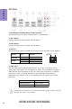
1 & 3 & 6. CPU_FAN (CPU cooling FAN Power Connector) & PWR_FAN (Power Cooling FAN Power Connector) & SYS_FAN (System Cooling FAN Power Connector) Chapter 2 Connect the CPU cooling fan cable to CPU_FAN. Connect the System cooling fan connector to SYS_FAN. Connect the Power cooling fan connector to PWR_FAN. Users please note that the fan connector supports the CPU cooling fan of 1.1A ~ 2.2A (26.4W max) at +12V. 2 & 7.
Connecting 24-pin power cable The ATX 24-pin connector allows you to connect to ATX v2.x power supply. Chapter 2 With ATX v2.x power supply, users please note that when installing 24-pin power cable, the latches of power cable and the ATX match perfectly. 24-pin power cable Connecting 4-pin power cable The ATX12V power connector is used to provide power to the CPU. When installing 4-pin power cable, the latches of power cable and the ATX12V match perfectly.
4. Front Panel Header Chapter 2 The front panel header (F_PANEL) provides a standard set of switch and LED headers commonly found on ATX or Micro ATX cases. Refer to the table below for information: Hard Drive Activity LED Connecting pins 1 and 3 to a front panel mounted LED provides visual indication that data is being read from or written to the hard drive. For the LED to function properly, an IDE drive should be connected to the onboard IDE interface.
5. SPK: Speaker header Connect the case speaker cable to SPK. Chapter 2 This concludes Chapter 2. The next chapter covers the BIOS.
Chapter 3 Using BIOS About the Setup Utility The BIOS (Basic Input and Output System) Setup Utility displays the system’s configuration status and provides you with options to set system parameters. The parameters are stored in battery-backed-up CMOS RAM that saves this information when the power is turned off. When the system is turned back on, the system is configured with the values you stored in CMOS.
Press the delete key to access BIOS Setup Utility. Chapter 3 Resetting the Default CMOS Values When powering on for the first time, the POST screen may show a “CMOS Settings Wrong” message. This standard message will appear following a clear CMOS data at factory by the manufacturer. You simply need to Load Default Settings to reset the default CMOS values. Note: Changes to system hardware such as different CPU, memories, etc. may also trigger this message.
In this manual, default values are enclosed in parenthesis. Submenu items are denoted by an icon . The default BIOS setting for this motherboard apply for most conditions with optimum performance. We do not suggest users change the default values in the BIOS setup and take no responsibility to any damage caused by changing the BIOS settings.
Main Menu This menu shows the information of BIOS and enables you to set the system language, date and time. Main Advanced Chipset M.I.B. X System Date System Time Security Save & Exit Choose the system default language BIOS Information System Language Boot English Fri 08/24/2012 19:02:34 : Select Screen Chapter 3 /Click: Select Item Enter/Dbl Click : Select +/- : Change Opt.
Advanced Menu The Advanced menu items allow you to change the settings for the CPU and other system. Advanced Chipset Legacy OpROM Support Launch PXE OpROM Launch Storage OpROM M.I.B. X Boot Disabled Enabled LAN Configuration PC Health Status Power Management Setup ACPI Settings CPU Configuration SATA Configuration USB Configuration Super IO Configuration Trusted Computing Security Save & Exit Enable or Disable Boot Option for Legacy Network Devices.
LAN Configuration The item in the menu shows the LAN-related information that the BIOS automatically detects. Main Advanced Chipset M.I.B. X Boot Security LAN Configuration Onboard LAN 1 Controller Enabled Chapter 3 : Select Screen /Click: Select Item Enter/Dbl Click : Select +/- : Change Opt. F1: General Help F2: Previous Values F3: Optimized Defaults F4: Save & Exit ESC/Right Click: Exit Onboard LAN 1 Controller (Enabled) Use this item to enable or disable Onboard LAN 1 controller.
PC Health Status On motherboards support hardware monitoring, this item lets you monitor the parameters for critical voltages, temperatures and fan speeds. Main Advanced Chipset M.I.B. X Boot Security Save & Exit PC Health Status : : : : : : +46 1198 RPM N/A +1.464 V +1.560 V +1.104 V : Select Screen /Click: Select Item Enter/Dbl Click : Select +/- : Change Opt.
Smart Fan start PWM value (64) This item is used to set the start PWM value of the smart fan. Smart Fan start PWM TEMP (40) This item is used to set the start temperature of the smart fan. DeltaT (+3) This item specifies the range that controls CPU temperature and keeps it from going so high or so low when smart fan works. Smart Fan Slope PWM value (7 PWM value / unite) This item is used to set the slope select PWM of the smart fan.
Power Management Setup This page sets up some parameters for system power management operation. Advanced Chipset M.I.B. X Boot Resume By RING Resume By PME Resume By USB 2.0 (S3) Resume By PS2 KB (S3) Resume By PS2 MS (S3) EUP Function Power LED Type Security Save & Exit About Resume by RING Power Management Setup Disabled Disabled Disabled Disabled Disabled Enabled Dual Color LED : Select Screen /Click: Select Item Enter/Dbl Click : Select +/- : Change Opt.
ACPI Settings The item in the menu shows the highest ACPI sleep state when the system enters suspend. Main Advanced Chipset M.I.B. X Boot ACPI Settings ACPI Sleep State S3 (Suspend to RAM) Security Save & Exit Select the highest ACPI sleep state the system will enter when the SUSPEND button is pressed. Chapter 3 : Select Screen /Click: Select Item Enter/Dbl Click : Select +/- : Change Opt.
CPU Configuration The item in the menu shows the CPU. Main Advanced Chipset M.I.B.
Enhanced Halt (ClE) (Disabled) Use this item to enable the CPU energy-saving function when the system is not running. SB Clock Spread Spectrum (Enabled) This item enables or disables the SB Clock Spread Spectrum. Press to return to the Advanced Menu page.
SATA Configuration Use this item to show the mode of serial SATA configuration options. Advanced Chipset M.I.B. X Boot Serial-ATA Controller SATA Mode SATA Port1 SATA Port2 SATA Port3 SATA Port4 SATA Port5 eSATA Security Save & Exit Enable or Disable Serial ATA Enabled IDE Mode Not Present Not Present Not Present Not Present Not Present Not Present : Select Screen /Click: Select Item Enter/Dbl Click : Select +/- : Change Opt.
USB Configuration Use this item to show the information of USB configuration. Main Advanced Chipset M.I.B III M.I.B. X Boot Boot Super IO Configuration USB Configuration Super Chip All USBIODevices SerialController Port 0 Configutation USB3.0 Parallel Port Configutation Legacy USB Support IT8728Enabled Enabled Enabled Security Security Chapter 3 : Select Screen : Select Screen /Click: Select Item /Click: Select Enter/Dbl Click : Item Select +/: Change Opt.
Super IO Configuration Use this item to show the information of Super IO configuration. Advanced Chipset M.I.B. X Boot Security Save & Exit Set Parameters of Serial Port 0 (COMA) Super IO Configuration Super IO Chip Serial Port 0 Configuration ITE IT8721F : Select Screen /Click: Select Item Enter/Dbl Click : Select +/- : Change Opt.
Device Mode (Standard Serial Port...) This item shows the information of the device mode. Press to return to the Super IO Configuration page. Press to return to the Advanced Menu page.
Trusted Computing Use this item to show the information of trusted computing configuration. Advanced Chipset Configuration Security Device Support M.I.B. X Boot Disabled Current Status Information SUPPORT TURNED OFF Security Save & Exit Enables or Disables BIOS support for security device. O.S. will not show Security Device. TCG EFI protocol and INT1A interface will not be available. : Select Screen /Click: Select Item Enter/Dbl Click : Select +/- : Change Opt.
Chipset Menu The chipset menu items allow you to change the settings for the North Bridge chipset, South Bridge chipset and other system. Main Advanced Chipset M.I.B. X Boot South Bridge Security Save & Exit South Bridge Parameters Chapter 3 : Select Screen /Click: /Click:Select SelectItem Item Enter/Dbl Click : Select +/- : Change Opt.
Case Open Warning (Disabled) This item enables or disables the warning if the case is opened up, and the item below indicates the current status of the case. Chassis Opened (No) This item indicates whether the case has been opened. Chapter 3 Press to return to the Chipset Menu page.
M.I.B. X (MB Intelligent BIOS X) Menu This page enables you to set the clock speed and system bus for your system. The clock speed and system bus are determined by the kind of processor you have installed in your system. Main Advanced Chipset M.I.B. X Boot Save & Exit Processor Power Planes and Voltage Controls M.I.B. X (MB Intelligent BIOS X) Processor Power Planes and Voltage Controls Memory Control HT Control NB Frequency/Voltage Chapter 3 Auto Detect DIMM/PCI Clk CPU Over-clocking Func.
Slam Time Mode (Auto) This item enables you to set slam time mode, this option is only for RB-C3, BL-C3, DAC3. VSSlamTime (Auto) This item specifies the time to wait for voltage stabilization during altvid transitions if a new VID is provided to the voltage regulator without ramping. 0:24N:3xDC [31:29]. Chapter 3 Press to return to the M.I.B. X Menu page. Memory Control Scroll to this item and press to view the following screen: Main Advanced Chipset M.I.B.
HT Control Scroll to this item and press to view the following screen: Main Advanced Chipset M.I.B. X Boot Security Current Width Up: Upstream Link Width Current Width Down: Downstream Link Width Current IO HT Freq: IO HT Frequency 16 bit Auto 16 bit Auto 2400Mhz Auto Chapter 3 : Select Screen /Click: Select Item Enter/Dbl Click : Select +/- : Change Opt.
NB Frequency/Voltage Scroll to this item and press to view the following screen: Advanced Chipset M.I.B. X Boot Current NB Frequency/Voltage NB Frequency NB Voltage Security Save & Exit NB Frequency 2000Mhz 1.2375V Auto Auto : Select Screen /Click: Select Item Enter/Dbl Click : Select +/- : Change Opt. F1: General Help F2: Previous Values F3: Optimized Defaults F4: Save & Exit ESC/Right Click: Exit Current NB Frequency/Voltage (2000Mhz 1.
Warning: Over-clocking components can adversely affect the reliability of the system and introduce errors into your system. Over-clocking can permanently damage the motherboard by generating excess heat in components that are run beyond the rated limits. Fail-Safe Procedures for Over-clocking Chapter 3 50 When end-users encounter failure after attempting over-clocking, please take the following steps to recover from it. 1. Shut down the computer. 2.
Boot Menu This page enables you to set the keyboard NumLock state. Advanced Chipset M.I.B.
Security Menu This page enables you to set setup administrator password and user password. Main Advanced Administrator Password Chipset M.I.B. X Boot Security Chapter 3 : Select Screen /Click: Select Item Enter/Dbl Click : Select +/- : Change Opt. F1: General Help F2: Previous Values F3: Optimized Defaults F4: Save & Exit ESC/Right Click: Exit Administrator Password This item allows you to set or change administrator password.
Save & Exit Menu This page enables you to exit system setup after saving or without saving the changes. Main Advanced Chipset M.I.B. X Boot Back to EZ Mode Security Save & Exit Go back to EZ Mode Load Non Disk Utility Save Options Save Changes Discard Changes Restore Defaults Save as User Defaults Restore User Defaults Boot Override : Select Screen /Click: Select Item Enter/Dbl Click : Select +/- : Change Opt.
Updating the BIOS You can download and install updated BIOS for this motherboard from the manufacturer’s Website. New BIOS provides support for new peripherals, improvements in performance, or fixes for known bugs. Install new BIOS as follows: Chapter 3 1 If your motherboard has a BIOS protection jumper, change the setting to allow BIOS flashing. 2 If your motherboard has an item called Firmware Write Protect in Advanced BIOS features, disable it.
Chapter 4 Using the Motherboard Software Auto-installing under Windows XP/Vista/7 The auto-install DVD-ROM makes it easy for you to install the drivers and software. The support software DVD-ROM disc loads automatically under Windows XP/Vista/ 7. When you insert the DVD-ROM disc in the DVD-ROM drive, the auto-run feature will automatically bring up the installation screen. The screen has four buttons on it: Setup, Utilities, Browse CD and Exit. Click “Exit” button to close the Auto-Setup window.
Click Next. The following screen appears: 3. Check the box next to the items you want to install. The default options are recommended. 4. Click Next to run the Installation Wizard. An item installation screen appears: 5. Follow the instructions on the screen to install the items. Chapter 4 2. Drivers and software are automatically installed in sequence. Follow the onscreen instructions, confirm commands and allow the computer to restart a few times to complete the installation.
Manual Installation Chapter 4 If the auto-install DVD-ROM does not work on your system, you can still install drivers through the file manager for your OS (for example, Windows Explorer). Look for the chipset and motherboard model, and then browse to the directory and path to begin installing the drivers. Most drivers have a setup program (SETUP.EXE) that automatically detects your operating system before installation. Other drivers have the setup program located in the operating system subfolder.
Memo Chapter 4 58 A970M-A DELUXE USER MANUAL
Chapter 5 Setting Up AMD SB950 RAID Configuration Setting Up a bootable RAID Array This section explains how to configure a bootable AMD RAID array. Setting Up the BIOS 1. Start your computer, then press Delete to enter the BIOS setup. The BIOS CMOS Setup Utility screen appears. Advanced Chipset M.I.B.
3. Use the arrow keys to select the SATA Configuration (see Figure 1.2) and globally set SATA Configuration to RAID. 4. Press F4 to save the configuration and exit. 5. Enter the RAID BIOS Setup by pressing Ctrl-F when prompted, and proceed to set up the AMD RAID BIOS as described in the next section. The PC reboots. Configuring the AMD RAID BIOS (Windows XP Installation) The AMD RAID BIOS set up lets you choose the RAID type and which hard drives you want to make part of the array.
3. Select [2], then select LD 1 in the following page. The Define LD Menu screen appears (Figure 1.4). FastBuild (tm) Utility (c) 2006 ATI Technology, Inc.
Assigning the Disks 1. Select the Assignment to Y to designate a free disk to be used as a RAID array disk. Figure 1.5 illustrates the Define a New Array screen after two disks have been assigned as RAID 0 array disks. FastBuild (tm) Utility (c) 2006 ATI Technology, Inc.
Press ESC to exit. The Main Menu screen appears (Figure 1.7). FastBuild (tm) Utility (c) 2006 ATI Technology, Inc. [ Main Menu ] View Drive Assignments..................[ 1 ] Define LD..........................................[ 2 ] Define LD..........................................[ 3 ] is going to REBOOT!4 ] ControllerSystem Configuration...................[ Are You Sure? Y - Reboot / Any Key - Back [ Keys Available ] Press 1..4 to Select Option [ESC] Exit Press Y to reboot.
Installing the RAID Drivers Your system may come with a Windows install CD that already includes AMD RAID drivers. If so, then this section is not relevant. If that is not the case (or you are trying to install a new version of Windows), then you will need an AMD RAID driver F6 install floppy. Check to see if one came with your system. If not, you can create one by downloading the appropriate driver package and following the steps in this section. 1. Copy all files in "...
a Insert the floppy that has the RAID driver, press S, then press Enter. The following Windows Setup screen appears: Windows Setup --------You have chosen to configure a SCSI Adapter for use with windows£¬ using a device support disk provided bu an adapter manufacturer. Select the SCSI Adapter you want from the following list, or press ESC to return to the previous screen. ATI AHCI Compatible RAID Controller-x86 platform ATI AHCI Compatible RAID Controller-x64 platform ENTER=Select F3=Exit Figure 1.
Memo Chapter 5 66 A970M-A DELUXE USER MANUAL
Chapter 6 Trouble Shooting Start up problems during assembly After assembling the PC for the first time you may experience some start up problems. Before calling for technical support or returning for warranty, this chapter may help to address some of the common questions using some basic troubleshooting tips. You may also log onto our ECS website for more information: http:// www.ecs.com.tw/ECSWebSite/Support/Support_FAQ.
2. From the BIOS setting, try to disable the Smartfan function to let the fan run at default speed. Doing a Load Optimised Default will also disable the Smartfan. Start up problems after prolong use After a prolong period of use your PC may experience start up problems again. This may be caused by breakdown of devices connected to the motherboard such as HDD, CPU fan, etc. The following tips may help to revive the PC or identify the cause of failure. 1. Clear the CMOS values using the CLR_CMOS jumper.
69 If fail, contact RMA CLR CMOS and restart. Yes Halt at POST screen Yes Check if monitor has display Yes Check if Power Supply Unit (PSU) is working Power Bu on is pressed but PC fails to start. - need to CLRCMOS. HDD problem.
Memo Chapter 6 70 A970M-A DELUXE USER MANUAL