Preface Copyright This publication, including all photographs, illustrations and software, is protected under international copyright laws, with all rights reserved. Neither this manual, nor any of the material contained herein, may be reproduced without written consent of the author. Version 1.0 Disclaimer The information in this document is subject to change without notice.
ii Declaration of Conformity This device complies with part 15 of the FCC rules. Operation is subject to the following conditions: • • This device may not cause harmful interference. This device must accept any interference received, including interference that may cause undesired operation. Canadian Department of Communications This class B digital apparatus meets all requirements of the Canadian Interferencecausing Equipment Regulations.
iii TABLE OF CONTENTS Preface i Chapter 1 1 Introducing the Motherboard 1 Introduction............................................................................................1 Feature.....................................................................................................2 Motherboard Components...................................................................6 Chapter 2 9 Installing the Motherboard 9 Safety Precautions................................................................
iv Save & Exit Menu.........................................................................46 Updating the BIOS.......................................................................47 49 Chapter 4 Using the Motherboard Software 49 About the Software DVD-ROM/CD-ROM.......................................49 Auto-installing under Windows XP/Vista/7.....................................49 Running Setup...............................................................................50 Manual Installation.....
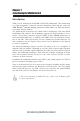
1 Chapter 1 Introducing the Motherboard Introduction Thank you for choosing the A990FXM-A DELUXE motherboard. This motherboard is a high performance, enhanced function motherboard that supports socket for AMD PhenomTM and later desktop processors (socket AM3+) for high-end business or personal desktop markets. The motherboard incorporates the AMD 990FX Northbridge (NB) and SB950 Southbridge (SB) chipsets. The Northbridge supports the HyperTransportTM 3.0 interface.
2 Feature Processor This motherboard uses a socket AM3+ that carries the following features: • Accommodates AMD PhenomTM and later desktop processors (socket AM3+) • Supports HyperTransportTM (HT) 3.0 interface speeds HyperTransportTM Technology is a point-to-point link between two devices, it enables integrated circuits to exchange information at much higher speeds than currently available interconnect technologies.
3 • Up to 32 GB per DIMM with maximum memory size up to 128 GB Audio • • 7.1+2 Channel High Definition Audio Codec Meets Microsoft WLP3.x (Windows Logo Program) audio requirements All DACs supports 44.1k/48k/96k/192kHz sample rate Software selectable 2.5V/3.2V/4.0V VREFOUT Direct Sound 3D. compatible Power Support: Digital: 3.3V; Analog: 5.0V • • • • Onboard LAN • • • Supports PCI ExpressTM 2.
4 Specifications CPU • • • AMD PhenomTM and later desktop processors (socket AM3+) Supports HyperTransportTM (HT) 3.0 interface speeds 140W TDP Chipset • NB: AMD 990FX SB: SB950 Memory • • • Dual-channel DDR3 memory architecture 4 x 240-pin DDR3 DIMM sockets support up to 128 GB Supports DDR3 DDR3 2133 (OC)/1866/1600/1333 SDRAM Expansion Slots • • • • 3 x PCI Express Gen2 x16 slots 2 x PCI Express x1 slots (Gen2) 1 x PCI slot Supported by AMD SB950 Express Chipset -6 x Serial ATA 6.
5 System BIOS Form Factor • • 1 x 3-pin SYS_FAN connector 1 x 3-pin PWR_FAN connector • • • • • • • • • AMI BIOS with 32Mb SPI Flash ROM Supports Plug and Play, STR (S3) / STD (S4) , Hardware monitor, Multi Boot Supports ACPI & DMI Audio, LAN, can be disabled in BIOS F7 hot key for boot up devices option Supports FSB adjustment, increase in a increase of 1MHz.
6 Motherboard Components The above image is for reference only; please take the actual motherboard for detailed parts.
7 Table of Motherboard Components LABEL COMPONENTS AMD Phenom TM and later desktop processors (socket AM3+) 1. CPU Socket 2. CPU_FAN 3. DDR3_1/2/3/4 4. BZ 5. ATX_POWER 6. POST 7. PWR_FAN 8. IDE 9. SATA1~6 10. PANEL 11. PWR_BTN 12. RST_BTN 13. F_USB2 14. CLR_CMOS CPU cooling fan connector 240-pin DDR3 SDRAM slots Buzzer Standard 24-pin ATX power connector POST Debug LED Power cooling fan connector Primary IDE channel Serial ATA 6.
8 Memo Introducing the Motherboard
9 Chapter 2 Installing the Motherboard Safety Precautions • • • • • Follow these safety precautions when installing the motherboard Wear a grounding strap attached to a grounded device to avoid damage from static electricity Discharge static electricity by touching the metal case of a safely grounded object before working on the motherboard Leave components in the static-proof bags they came in Hold all circuit boards by the edges.
10 Do not over-tighten the screws as this can stress the motherboard. Checking Jumper Settings This section explains how to set jumpers for correct configuration of the motherboard. Setting Jumpers Use the motherboard jumpers to set system configuration options. Jumpers with more than one pin are numbered. When setting the jumpers, ensure that the jumper caps are placed on the correct pins. The illustrations show a 2-pin jumper. When the jumper cap is placed on both pins, the jumper is SHORT.
11 Checking Jumper Settings The following illustration shows the location of the motherboard jumpers. Pin 1 is labeled. Name Type Description Setting (default) 1-2: NORMAL CLR_CMOS 3-pin Clear CMOS 2-3: CLEAR 1 2 3 Before clearing the CMOS, make sure to CLR_CMOS turn off the system. To avoid the system unstability after clearing CMOS, we recommend users to enter the main BIOS setting page to “Load Default Settings” and then “Save Changes and Exit”.
12 Installing Hardware Installing the Processor Caution: When installing a CPU heatsink and cooling fan make sure that you DO NOT scratch the motherboard or any of the surface-mount resistors with the clip of the cooling fan. If the clip of the cooling fan scrapes across the motherboard, you may cause serious damage to the motherboard or its components. On most motherboards, there are small surface-mount resistors near the processor socket, which may be damaged if the cooling fan is carelessly installed.
13 CPU Installation Procedure The following illustration shows CPU installation components. 1 Install your CPU. Pull up the lever away from the socket and lift up to 90-degree angle. Locate the CPU cut edge (the corner with the pin hold noticeably missing). Align and insert the CPU correctly. Press the lever down and apply thermal grease on top of the CPU. Put the CPU Fan down on the retention module and snap the four retention legs of the cooling fan into place.
14 Installation Procedure Refer to the following to install the memory modules. 1 2 3 4 5 6 This motherboard supports unbuffered DDR3 SDRAM only. Push the latches on each side of the DIMM slot down. Align the memory module with the slot. The DIMM slots are keyed with notches and the DIMMs are keyed with cutouts so that they can only be installed correctly. Check that the cutouts on the DIMM module edge connector match the notches in the DIMM slot.
15 Expansion Slots Installing Add-on Cards The slots on this motherboard are designed to hold expansion cards and connect them to the system bus. Expansion slots are a means of adding or enhancing the motherboard’s features and capabilities. With these efficient facilities, you can increase the motherboard’s capabilities by adding hardware that performs tasks that are not part of the basic system.
16 Follow these instructions to install an add-on card: 1 2 3 Remove a blanking plate from the system case corresponding to the slot you are going to use. Install the edge connector of the add-on card into the expansion slot. Ensure that the edge connector is correctly seated in the slot. Secure the metal bracket of the card to the system case with a screw.
17 Connecting Optional Devices Refer to the following for information on connecting the motherboard’s optional devices: SATA1~6: Serial ATA connectors These connectors are used to support the new Serial ATA devices for the highest data transfer rates (6.0 Gb/s), simpler disk drive cabling and easier PC assembly. It eliminates limitations of the current Parallel ATA interface. But maintains register compatibility and software compatibility with Parallel ATA.
18 F_USB1~2: Front Panel USB 2.0 headers The motherboard has six USB ports installed on the rear edge I/O port array. Additionally, some computer cases have USB ports at the front of the case. If you have this kind of case, use auxiliary USB connector to connect the front-mounted ports to the motherboard. Unlike F_USB2 in this mainboard, F_USB1 supports EZ Charger technology (optional), provides 3 times current than general USB port in off mode for USB devices.
19 USB3F: Front Panel USB 3.0 header This Motherboard implements one USB 3.0 header supporting 2 extra front USB 3.0 ports, which delivers 5Gb/s transfer rate.
20 Installing a Hard Disk Drive/CD-ROM/SATA Hard Drive This section describes how to install IDE devices such as a hard disk drive and a CDROM drive. About IDE Devices Your motherboard has one IDE interface. An IDE ribbon cable supporting two IDE devices is bundled with the motherboard. You must orient the cable connector so that the pin1 (color) edge of the cable corresponds to the pin 1 of the I/O port connector.
21 Refer to the illustration below for proper installation: 1 2 3 Attach either cable end to the connector on the motherboard. Attach the other cable end to the SATA hard drive. Attach the SATA power cable to the SATA hard drive and connect the other end to the power supply. * For reference only This motherboard supports the “Hot-Plug” function.
22 Connecting I/O Devices The backplane of the motherboard has the following I/O ports: Bluetooth Used to connect to Bluetooth devices. PS/2 mouse and keyboard combo connector Connect the PS/2 Keyboard or PS/2 Mouse to the PS/2 combo port. CLR_COMS_BTN Use the CLR_CMOS button to clear CMOS. USB 2.0 Ports Use the USB 2.0 ports to connect USB 2.0 devices. USB 3.0 Ports Use the USB 3.0 ports to connect USB3.0 devices.
23 Connecting Case Components After you have installed the motherboard into a case, you can begin connecting the motherboard components. Refer to the following: 1 Connect the CPU cooling fan cable to CPU_FAN. 2 Connect the standard power supply connector to ATX_POWER. 3 Connect the case switches and indicator LEDs to the PANEL. 4 Connect the system cooling fan connector to SYS_FAN. 5 Connect the auxiliary case power supply connector to ATX12V. 6 Connect the power cooling fan connector to PWR_FAN.
24 Connecting 8/4-pin power cable Users please note that the 8-pin and 4-pin power cables can both be connected to the ATX12V connector. When installing 8-pin power cable, the latches of power cable and the ATX12V connector match perfectly. * For reference only 8-pin power cable When installing 4-pin power cable, the latch falls on the left side of the ATX12V connector.
25 SYS_FAN: FAN Power Connector Pin 1 2 3 Signal Name Function System Ground Power +12V Sensor GND +12V Sense PWR_FAN: FAN Power Connector Pin 1 2 3 Signal Name Function System Ground Power +12V Sensor GND +12V Sense ATX12V: ATX 12V Power Connector Pin Signal Name Pin 1 2 3 4 Ground 5 6 7 8 Ground Ground Ground Signal Name +12V +12V +12V +12V Installing the Motherboard
26 Front Panel Header The front panel header (F_PANEL) provides a standard set of switch and LED headers commonly found on ATX or Micro ATX cases.
27 Chapter 3 Using BIOS About the Setup Utility The computer uses the latest “American Megatrends Inc. ” BIOS with support for Windows Plug and Play. The CMOS chip on the motherboard contains the ROM setup instructions for configuring the motherboard BIOS. The BIOS (Basic Input and Output System) Setup Utility displays the system’s configuration status and provides you with options to set system parameters.
28 Press the delete key to access the BIOS Setup Utility. Aptio Setup Utility - Copyright (C) 2010 American Megatrends, Inc. Main Advanced Chipset M.I.B X Boot Security System Date System Time Save & Exit Choose the system default language BIOS Information [ Mon 07/18/2011] [05:44:29] :Select Screen :Select Item Enter : Select +/- : Change Opt. F1:General Help F2:Previous Value F3:Optimized Defaults F4:Save & Exit ESC:Exit Version 2.10.1208. Copyright (C) 2010 American Megatrends, Inc.
29 Using BIOS When you start the Setup Utility, the main menu appears. The main menu of the Setup Utility displays a list of the options that are available. A highlight indicates which option is currently selected. Use the cursor arrow keys to move the highlight to other options. When an option is highlighted, execute the option by pressing . Some options lead to pop-up dialog boxes that prompt you to verify that you wish to execute that option.
30 Main Menu When you enter the BIOS Setup program, the main menu appears, giving you an overview of the basic system information. Select an item and press to display the submenu. Aptio Setup Utility - Copyright (C) 2010 American Megatrends, Inc. Main Advanced Chipset M.I.B X Boot Security System Date System Time Save & Exit Choose the system default language BIOS Information [ Mon 07/18/2011] [05:44:29] :Select Screen :Select Item Enter : Select +/- : Change Opt.
31 Advanced Menu The Advanced menu items allow you to change the settings for the CPU and other system. Aptio Setup Utility - Copyright (C) 2010 American Megatrends, Inc. Main Advanced Chipset Legacy OpROM Support Launch PXE OpROM Launch Storage OpROM M.I.B X Boot Security Save & Exit Enable or Disable Boot Option for Leagacy Network Devices.
32 PC Health Status On motherboards support hardware monitoring, this item lets you monitor the parameters for critical voltages, temperatures and fan speeds. Aptio Setup Utility - Copyright (C) 2010 American Megatrends, Inc. Main Advanced Chipset M.I.B X Boot Security Save & Exit PC Health Status Smart Fan Function CPU Tcontrol CPU Fan Speed System Fan Speed CPU Vcore DIMM Voltage NB Voltage : +58 °C : 3000 RPM : N/A : +1.452V : +1.572V : +1.
33 Smart Fan Mode (Normal) This item allows you to select the fan mode (Normal, Quiet, Silent, or Manual) for a better operation environment. If you choose Normal mode, the fan speed will be auto adjusted depending on the CPU temperature. If you choose Quite mode, the fan speed will be auto minimized for quiet environment. If you choose Silent mode, the fan speed will be auto restricted to make system more quietly. If you choose Manual mode, the fan speed will be adjust depending on users’ parameters.
34 Power Management Setup This page sets up some parameters for system power management operation. Aptio Setup Utility - Copyright (C) 2010 American Megatrends, Inc. Main Advanced Chipset M.I.B X Boot Security Save & Exit About Resume by PCI/PCI-E/Lan/Ext. USB3.0 PME Power Management Setup Resume By PME Resume By USB2.
35 ACPI Configuration The item in the menu shows the highest ACPI sleep state when the system enters suspend. Aptio Setup Utility - Copyright (C) 2010 American Megatrends, Inc. Main Advanced Chipset M.I.B X Boot Security Save & Exit ACPI Configuration ACPI Sleep State [S3 (Suspend to RAM)] Select the highest ACPI sleep state the system will enter when the SUSPEND button is pressed. :Select Screen :Select Item Enter : Select +/- : Change Opt.
36 CPU Configuration Scroll to this item and press to view the following screen: Aptio Setup Utility - Copyright (C) 2010 American Megatrends, Inc. Main Advanced Chipset M.I.
37 SATA Configuration Use this item to show the mode of serial-ATA configuration options. Aptio Setup Utility - Copyright (C) 2010 American Megatrends, Inc. Main Advanced Chipset M.I.
38 USB Configuration Scroll to this item and press to view the following screen: Aptio Setup Utility - Copyright (C) 2010 American Megatrends, Inc. Main Advanced Chipset M.I.B X Boot Security Save & Exit Enabled/Disabled All USB Devices USB Configuration All USB Devices USB 3.0 Support Legacy USB Support Bluetooth Function [Enabled] [Enabled] [Enabled] [Enabled] :Select Screen :Select Item Enter : Select +/- : Change Opt.
39 Chipset Menu The chipset menu items allow you to change the settings for the South Bridge chipset and other system. Aptio Setup Utility - Copyright (C) 2010 American Megatrends, Inc. Main Advanced Chipset M.I.B X Boot Security Save & Exit South Bridge Parameters South Bridge :Select Screen :Select Item Enter : Select +/- : Change Opt. F1:General Help F2:Previous Value F3:Optimized Defaults F4:Save & Exit ESC:Exit Version 2.10.1208. Copyright (C) 2010 American Megatrends, Inc.
40 M.I.B X(MB Intelligent BIOS X) This page enables you to set the clock speed and system bus for your system. The clock speed and system bus are determined by the kind of processor you have installed in your system. Aptio Setup Utility - Copyright (C) 2010 American Megatrends, Inc. Main Advanced Chipset M.I.B X Boot Security Save & Exit Processor Power Planes and Voltage Controls M.I.
41 AltVid (0) This item specifies the VID driven to the VDD power plane(s) while in the low power state 0:24N:3xDC[6:0]. Slam Time Mode (Auto) This item enables you to set slam time mode, this option is only for RB-C3, BLC3, DA-C3. VSSlamTime (Auto) This item specifies the time to wait for voltage stabilization during altvid transitions if a new VID is provided to the voltage regulator without ramping. 0:24N:3xDC [31:29] Press to return to the M.I.B X Menu page.
42 HT Control Scroll to this item and press to view the following screen: Aptio Setup Utility - Copyright (C) 2010 American Megatrends, Inc. Main Advanced Chipset M.I.B X Boot Security Save & Exit Set Upstream Link Width. HT control Current Width Up: Upstream Link Width Current Width Down: Downstream Link Width Current IO HT Freq: IO HT Frequency 16 bit [Auto] 16 bit [Auto] 2600MHz [Auto] :Select Screen :Select Item Enter : Select +/- : Change Opt.
43 CPU Voltage (Default) This item allows user to adjust CPU voltage when enabled. NB Voltage (Default) This item allows user to adjust NB voltage when enabled. VDIMM Voltage (Default) This item allows user to adjust DIMM voltage when enabled. SB Voltage (Default) This item allows user to adjust SB voltage when enabled. CPU Current Voltage (1.452V) This item shows the current CPU voltage. VDIMM Current Voltage (1.572V) This item displays the current DIMM voltage.
44 Boot Menu This page enables you to set the keyboard NumLock state and Boot device priority. Aptio Setup Utility - Copyright (C) 2010 American Megatrends, Inc. Main Advanced Chipset M.I.
45 Security Menu This page enables you to set setup administrator and password. Aptio Setup Utility - Copyright (C) 2010 American Megatrends, Inc. Main Advanced Chipset M.I.B X Boot Security Save & Exit Set Setup Administrator Password Administrator Password :Select Screen :Select Item Enter : Select +/- : Change Opt. F1:General Help F2:Previous Value F3:Optimized Defaults F4:Save & Exit ESC:Exit Version 2.10.1208. Copyright (C) 2010 American Megatrends, Inc.
46 Save & Exit Menu This page enables you to exit system setup after saving or without saving the changes. Aptio Setup Utility - Copyright (C) 2010 American Megatrends, Inc. Main Advanced Chipset M.I.B X Boot Security Save & Exit Save Changes and Exit Discard Changes and Exit Save Changes and Reset Discard Changes and Reset Exit system setup after saving the changes. Save Options Save Changes Discard Changes :Select Screen :Select Item Enter : Select +/- : Change Opt.
47 Updating the BIOS You can download and install updated BIOS for this motherboard from the manufacturer’s Web site. New BIOS provides support for new peripherals, improvements in performance, or fixes for known bugs. Install new BIOS as follows: 1 If your motherboard has a BIOS protection jumper, change the setting to allow BIOS flashing. 2 If your motherboard has an item called Firmware Write Protect in Advanced BIOS features, disable it. (Firmware Write Protect prevents BIOS from being overwritten.
48 Memo Using BIOS
49 Chapter 4 Using the Motherboard Software About the Software DVD-ROM/CD-ROM The support software DVD-ROM/CD-ROM that is included in the motherboard package contains all the drivers and utility programs needed to properly run the bundled products. Below you can find a brief description of each software program, and the location for your motherboard version. More information on some programs is available in a README file, located in the same directory as the software.
50 Drivers Setup Click the Setup button to run the software installation program. Select from the menu which software you want to install. Utilities Click the Utilities button to display the application software and other software utilities that are available on the disk. Select the sofware you want to install then follow installation procedure. Browse CD The Browse CD button is the standard Windows command that allows you to open Windows Explorer and show the contents of the support disk.
51 2. Click Next. The following screen appears: 3. Check the box next to the items you want to install. The default options are recommended. 4. Click Next run the Installation Wizard. An item installation screen appears: 5. Follow the instructions on the screen to install the items. Drivers and software are automatically installed in sequence. Follow the onscreen instructions, confirm commands and allow the computer to restart a few times to complete the installation.
52 Windows Vista/7 will appear below UAC (User Account Control) message after the system restart. You must select “Allow” to install the next driver. Continue this process to complete the drivers installation. Manual Installation Insert the disk in the DVD-ROM/CD-ROM drive and locate the PATH.DOC file in the root directory. This file contains the information needed to locate the drivers for your motherboard.
53 Chapter 5 Setting Up AMD SB950 RAID Configuration Setting Up a bootable RAID Array This section explains how to configure a bootable AMD RAID array. Setting Up the BIOS 1 Start your computer, then press Delete to enter the BIOS setup. The BIOS CMOS Setup Utility screen appears. Aptio Setup Utility - Copyright (C) 2010 American Megatrends, Inc. Main Advanced Chipset M.I.
54 4 Press F4 to save the configuration and exit. The PC reboots. 5 Enter the RAID BIOS Setup by pressing Ctrl-F when prompted, and proceed to set up the AMD RAID BIOS as described in the next section. Configuring the AMD RAID BIOS (Windows XP Installation) The AMD RAID BIOS set up lets you choose the RAID type and which hard drives you want to make part of the array. Entering the RAID BIOS Setup: 1 Wait until you see the RAID software prompting you to press Ctrl-F.
55 3 Select [2], then select LD 1 in the following page. The Define LD Menu screen appears (Figure 1.4). FastBuild (tm) Utility (c) 2006 ATI Technology, Inc.
56 Assigning the Disks 1. Select the Assignment to Y to designate a free disk to be used as a RAID array disk. Figure 1.5 illustrates the Define a New Array screen after two disks have been assigned as RAID 0 array disks. FastBuild (tm) Utility (c) 2006 ATI Technology, Inc.
57 3. Press ESC to exit. The Main Menu screen appears (Figure 1.7). [ Main Menu ] View Drive Assignments..................[ 1 ] Define LD..........................................[ 2 ] Define LD..........................................[ 3 ] is going to REBOOT!4 ] ControllerSystem Configuration...................[ Are You Sure? Y - Reboot / Any Key - Back [ Keys Available ] Press 1..4 to Select Option Figure 1.7 4 [ESC] Exit Main Menu Press Y to reboot. The following screen appears (Figure 1.8).
58 Installing the RAID Drivers Your system may come with a Windows install CD that already includes AMD RAID drivers. If so, then this section is not relevant. If that is not the case (or you are trying to install a new version of Windows), then you will need an AMD RAID driver F6 install floppy. Check to see if one came with your system. If not, you can create one by downloading the appropriate driver package and following the steps in this section. 1 Copy all files in "...
59 The following Windows Setup screen appears: Windows Setup --------You have chosen to configure a SCSI Adapter for use with windows£¬ using a device support disk provided bu an adapter manufacturer. Select the SCSI Adapter you want from the following list, or press ESC to return to the previous screen. ATI AHCI Compatible RAID Controller-x86 platform ATI AHCI Compatible RAID Controller-x64 platform ENTER=Select F3=Exit Figure 1.
60 Memo AMD RAID Configuration
61 Chapter 6 ATI CrossFireXTM Technology Support This motherboard supports the ATI CrossFireX TM Technology that allows you to install multi-graphics processing units (GPU) graphics cards. Follow the installation procedures in this section. Requirements 1 2 3 4 Two or three identical CrossFireXTM ready graphic cards are needed for the setup of 2-way / 3-way CrossFireXTM configuration. You would need one or two CrossfireXTM bridge cable.
62 B. For 3-way configuration, two CrossFireTM Bridges are needed to connect the three graphic cards. 3. Connect the cable from your monitors to the CrossFireXTM ready graphics card installed on the PCIEX16_1 slot. Monitor Cable * For reference only Monitor Cable * For reference only 4. Connect an auxiliary power source from the power supply to the graphics cards.
63 The CatalystTM Control Center Dialog Box To enable CrossFireXTM: • • • • Install ATI graphic card driver. Enter the CatalystTM Control Center Dialog Box. check the “Enable CrossFireXTM” item. Click OK to apply.
64 Memo ATI CrossFireXTM Technology Support
65 Chapter 7 Trouble Shooting Start up problems during assembly After assembling the PC for the first time you may experience some start up problems. Before calling for technical support or returning for warranty, this chapter may help to address some of the common questions using some basic troubleshooting tips. a) System does not power up and the fans are not running. 1.Disassemble the PC to remove the VGA adaptor card, DDR memory, LAN, USB and other peripherals including keyboard and mouse.
66 2. From the BIOS setting, try to disable the Smartfan function to let the fan run at default speed. Doing a Load Optimised Default will also disable the Smartfan. Start up problems after prolong use After a prolong period of use your PC may experience start up problems again. This may be caused by breakdown of devices connected to the motherboard such as HDD, CPU fan, etc. The following tips may help to revive the PC or identify the cause of failure. 1. Clear the CMOS values using the CLR_CMOS jumper.
If fail, contact RMA CLR CMOS and restart. Yes Halt at POST screen Yes Check if monitor has display Yes Check if Power Supply Unit (PSU) is working Power Bu on is pressed but PC fails to start. - need to CLRCMOS. HDD problem.
68 Memo Trouble Shooting
69 POST Code Checkpoints The POST code checkpoints are the largest set of checkpoints during the BIOS pre-boot process.
70 35 36 37 CPU post-memory initialization. Boot Strap Processor (BSP) selection CPU post-memory initialization.
71 FB-FF 1 1 2 Reserved for future AMI error codes Memory not Installed Memory was installed twice (InstallPeiMemory routine in PEI Core called twice) Recovery started 3 3 7 4 4 60 61 DXEIPL was not found DXE Core Firmware Volume was not found Reset PPI is not available Recovery failed S3 Resume failed DXE Core is started NVRAM initialization 62 63 64 65 66 67 68 Installation of the South Bridge Runtime Services CPU DXE initialization is started CPU DXE initialization (CPU module specific) CPU DXE init
72 9E-9F Reserved for future AMI codes A0 A1 IDE initialization is started IDE Reset A2 A3 IDE Detect IDE Enable A4 SCSI initialization is started A5 A6 SCSI Reset SCSI Detect A7 SCSI Enable A8 A9 Setup Verifying Password Start of Setup AA AB Reserved for ASL (see ASL Status Codes section below) Setup Input Wait AC Reserved for ASL (see ASL Status Codes section below) AD AE Ready To Boot event Legacy Boot event AF B0 Exit Boot Services event Runtime Set Virtual Address MAP Begin B1 Ru