Preface Copyright This publication, including all photographs, illustrations and software, is protected under international copyright laws, with all rights reserved. Neither this manual, nor any of the material contained herein, may be reproduced without written consent of the author. Version 1.0 Disclaimer The information in this document is subject to change without notice.
ii Declaration of Conformity This device complies with part 15 of the FCC rules. Operation is subject to the following conditions: • • This device may not cause harmful interference, and This device must accept any interference received, including interference that may cause undesired operation. Canadian Department of Communications This class B digital apparatus meets all requirements of the Canadian Interference-causing Equipment Regulations.
iii TABLE OF CONTENTS Preface i Chapter 1 1 Introducing the Motherboard 1 Introduction................................................................................................1 Features.......................................................................................................2 Motherboard Components.......................................................................4 Chapter 2 7 Installing the Motherboard 7 Safety Precautions.....................................................
iv Advanced Chipset Features.........................................................31 Integrated Peripherals.................................................................34 Power Management Setup...........................................................37 PNP/PCI Configurations.............................................................41 PC Health Status..........................................................................42 Frequency/Voltage Control.............................................
1 Chapter 1 Introducing the Motherboard Introduction Thank you for choosing C7VCM2 motherboard of great performance and with enhanced function. This motherboard has onboard C7 processor with a Mini-ITX form factor of 170 x 170 mm. The motherboard integrates the VIA CN700 Northbridges and VT8237R Plus Southbridge. The Northbridge supports a Front Side Bus (FSB) frequency of 400 MHz. The memory controller supports DDR2 memory DIMM frequencies of 533/400.
2 Features Processor This motherboard uses onboard C7 processor that carries the following features: • • Accommodates VIA C7 processor Supports a system bus (FSB) of 400 MHz Chipset The CN700 Northbridge (NB) and VT8237R Plus Southbridge (SB) chipsets are based on an innovative and scalable architecture with proven reliability and performance. CN700(NB) • • • Supports 400 MHz FSB VIA C7 Processor Supports Host dynamic bus inversion (DBI) Supports AGP v3.
3 Expansion Options The motherboard comes with the following expansion options: • • • One 32-bit PCI slot Two IDE connectors which support four IDE devices Two 7-pin SATA connectors The motherboard supports Ultra DMA bus mastering with transfer rates of 133/100/66 33MB/s. Integrated I/O The motherboard has a full set of I/O ports and connectors: • • • • • • • Two PS/2 ports for mouse and keyboard One serial port One parallel port One VGA port Four back-panle USB2.
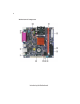
4 Motherboard Components Introducing the Motherboard
5 Table of Motherboard Components LABEL 1. DDRII1 2. ATX_POWER2 3. IDE2 4. IDE1 5. PANEL1 6. SATA1~2 7. CLR_CMOS1 8. PCI1 9. AUDIO1 10. F_USB1~2 11. IR1 12. COM2 13.
6 Memo Introducing the Motherboard
7 Chapter 2 Installing the Motherboard Safety Precautions • • • • • Follow these safety precautions when installing the motherboard Wear a grounding strap attached to a grounded device to avoid damage from static electricity Discharge static electricity by touching the metal case of a safely grounded object before working on the motherboard Leave components in the static-proof bags they came in Hold all circuit boards by the edges.
8 Do not over-tighten the screws as this can stress the motherboard. Checking Jumper Settings This section explains how to set jumpers for correct configuration of the motherboard. Setting Jumpers Use the motherboard jumpers to set system configuration options. Jumpers with more than one pin are numbered. When setting the jumpers, ensure that the jumper caps are placed on the correct pins. The illustrations show a 2-pin jumper. When the jumper cap is placed on both pins, the jumper is SHORT.
9 Checking Jumper Settings The following illustration shows the location of the motherboard jumpers. Pin 1 is labeled. Jumper Settings Jumper Type Description Setting (default) 1-2: NORMAL CLR_CMOS1 3-pin CLEAR CMOS 2-3: CLEAR CMOS Before clearing the CMOS, make sure to turn the system off. To avoid the system unstability after clearing CMOS, we recommend users to enter the main BIOS setting page to “Load Optimal Defaults” and then “Save Changes and Exit”.
10 Connecting Case Components After you have installed the motherboard into a case, you can begin connecting the motherboard components. Refer to the following: 1 2 3 Connect the CPU cooling fan cable to CPUFAN1. Connect the case switches and indicator LEDs to the PANEL1. Connect the standard power supply connector to ATX_POWER1.
11 ATX_POWER1: ATX 20-pin Power Connector Pin Signal Name Pin Signal Name VCC3 VCC3 11 12 -12V GND 13 GND 4 VCC 14 PS-ON# 5 6 7 8 9 10 GND VCC GND 15 16 17 18 19 20 GND GND GND 1 2 VCC3 3 PWROK 5VSB +12V -5V VCC VCC Front Panel Header The front panel header (PANEL1) provides a standard set of switch and LED headers commonly found on ATX or micro-ATX cases.
12 Power/Sleep/Message waiting LED Connecting pins 2 and 4 to a single or dual-color, front panel mounted LED provides power on/off, sleep, and message waiting indication. Reset Switch Supporting the reset function requires connecting pin 5 and 7 to a momentary-contact switch that is normally open. When the switch is closed, the board resets and runs POST. Power Switch Supporting the power on/off function requires connecting pins 6 and 8 to a momentarycontact switch that is normally open.
13 Installation Procedure Refer to the following to install the memory modules. 1 2 3 4 5 This motherboard supports unbuffered DDR2 SDRAM only. Push the latches on each side of the DIMM slot down. Align the memory module with the slot. The DIMM slots are keyed with notches and the DIMMs are keyed with cutouts so that they can only be installed correctly. Check that the cutouts on the DIMM module edge connector match the notches in the DIMM slot.
14 Table A: DDR2 (memory module) QVL (Qualified Vendor List) The following DDR2 memory modules have been tested and qualified for use with this motherboard.
15 Installing a Hard Disk Drive/CD-ROM/SATA Hard Drive This section describes how to install IDE devices such as a hard disk drive and a CD-ROM drive. About IDE Devices Your motherboard has a primary and secondary IDE channel interface (IDE1 and IDE2). An IDE ribbon cable supporting two IDE devices is bundled with the motherboard. You must orient the cable connector so that the pin1 (color) edge of the cable corresponds to the pin 1 of the I/O port connector.
16 About SATA Connectors Your motherboard features two SATA connectors supporting a total of two drives. SATA refers to Serial ATA (Advanced Technology Attachment) is the standard interface for the IDE hard drives which are currently used in most PCs. These connectors are well designed and will only fit in one orientation. Locate the SATA connectors on the motherboard and follow the illustration below to install the SATA hard drives.
17 Installing Add-on Cards The slots on this motherboard are designed to hold expansion cards and connect them to the system bus. Expansion slots are a means of adding or enhancing the motherboard’s features and capabilities. With these efficient facilities, you can increase the motherboard’s capabilities by adding hardware that performs tasks that are not part of the basic system. PCI1 Slot This motherboard is equipped with one PCI slot.
18 Follow these instructions to install an add-on card: 1 2 3 Remove a blanking plate from the system case corresponding to the slot you are going to use. Install the edge connector of the add-on card into the expansion slot. Ensure that the edge connector is correctly seated in the slot. Secure the metal bracket of the card to the system case with a screw.
19 Connecting Optional Devices Refer to the following for information on connecting the motherboard’s optional devices: IR1: Infrared header Pin Signal Name 1 2 3 4 5 6 Not Assigned Function Key Not assigned No pin +5V IR Power GND Ground IR_TX IrDA serial output IR_RX IrDA serial input COM2: Onboard serial port header Connect a serial port extension bracket to this header to add a second serial port to your system.
20 AUDIO1: Front Panel Audio header This header allows the user to install auxiliary front-oriented microphone and line-out ports for easier access.
21 Connecting I/O Devices The backplane of the motherboard has the following I/O ports: PS2 Mouse Use the upper PS/2 port to connect a PS/2 pointing device. PS2 Keyboard Use the lower PS/2 port to connect a PS/2 keyboard. Parallel Port Use the LPT1 to connect printer or other parallel communications devices. (LPT1) Serial Ports (COM1) Use the COM ports to connect serial devices such as mice or fax/ modems. VGA Port Connect your monitor to the VGA port.
22 Memo Installing the Motherboard
23 Chapter 3 Using BIOS About the Setup Utility The computer uses the latest Award BIOS with support for Windows Plug and Play. The CMOS chip on the motherboard contains the ROM setup instructions for configuring the motherboard BIOS. The BIOS (Basic Input and Output System) Setup Utility displays the system’s configuration status and provides you with options to set system parameters. The parameters are stored in battery-backed-up CMOS RAM that saves this information when the power is turned off.
24 Press DEL to enter SETUP Pressing the delete key accesses the BIOS Setup Utility: Phoenix-AwardBIOS CMOS Setup Utility: Standard CMOS Features Advanced BIOS Features Frequency/Voltage Control Load Fail-Safe Defaults Advanced Chipset Features Load Optimized Defaults Integrated Peripherals Set Supervisor Password Power Management Setup Set User Password PnP/PCI Configurations Save & Exit Setup PC Health Status Exit Without Saving Esc: Quit F10: Save & Exit Setup : Select Item Time, Date, Hard
25 Updating the BIOS You can download and install updated BIOS for this motherboard from the manufacturer’s Web site. New BIOS provides support for new peripherals, improvements in performance, or fixes for known bugs. Install new BIOS as follows: 1 2 3 4 5 6 7 8 If your motherboard has a BIOS protection jumper, change the setting to allow BIOS flashing. If your motherboard has an item called Firmware Write Protect in Advanced BIOS features, disable it.
26 Standard CMOS Features This option displays basic information about your system.
27 If you are setting up a new hard disk drive that supports LBA mode, more than one line will appear in the parameter box. Choose the line that lists LBA for an LBA drive. IDE Channel 0/1 Master/Slave IDE/Extended IDE Drives (Auto) Leave this item at Auto to enable the system to automatically detect and configure IDE devices on the channel.
28 Advanced BIOS Features This option defines advanced information about your system.
29 Hard Disk Boot Priority (Press Enter) Scroll to this item and press to view the following screen: Phoenix-AwardBIOS CMOS Setup Utility Hard Disk Boot Priority Item Help 1.Ch0 M. : ST3802110A 2. Bootable Add-in Cards Menu Level Use < > or < > to select a device, then press <+> to move it up, or <-> to move it down the list. Press to exit this menu.
30 • Typematic Delay (Msec): Use this item to define how many milliseconds must elapse before a held-down key begins generating repeat characters. Security Option (Setup) If you have installed password protection, this item defines if the password is required at system start up, or if it is only required when a user tries to enter the Setup Utility. MPS Version Control For OS (1.4) This item specifies which version of MPS of (Multi-Processor Specification) this motherboard will use.
31 Advanced Chipset Features These items define critical timing parameters of the motherboard. You should leave the items on this page at their default values unless you are very familiar with the technical specifications of your system hardware. If you change the values incorrectly, you may introduce fatal errors or recurring instability into your system.
32 DRAM Clock (By SPD) This item sets the DRAM clock module. DRAM Timing (Auto By SPD) This item selects the DRAM timing mode. • SDRAM CAS Latency (DDR/DDR 2.5/4): This item determines the operation of DDR SDRAM memory CAS (column address strobe). It is recommended that you leave this item at the default value. The 2.5T setting requires faster memory that secifically supports this mode.
33 CPU & PCI Bus Control (Press Enter) Scroll to this item and press to view the following screen: Phoenix-AwardBIOS CMOS Setup Utility CPU & PCI Bus Control PCI Master 0 WS Write PCI Delay Transaction VLink mode selection VLink 8X Support DRDY_Timing [Enabled] [Enabled] [By Auto] [Enabled] [Default] Item Help Menu Level : Move Enter: Select +/-/PU/PD:Value F10:Save ESC:Exit F1: General Help F5:Previous Values F6:Fail-Safe Defaults F7:Optimized Defaults PCI Master 0 WS Write (Enabled) This item
34 Integrated Peripherals These options display items that define the operation of peripheral components on the system’s input/output ports.
35 IDE Prefetch Mode (Enabled) The onboard IDE drive interface supports IDE prefetching, for faster drive access. If you install a primary and secondary add-on interface, set this field to Disable if the interface does not support prefetching. Primary/Secondary Master/Slave PIO (Auto) Each IDE channel supports a master device and a slave device. These four items let you assign the kind of PIO (Programmed Input/Output) was used by the IDE devices.
36 USB Emulation (ON) • USB Keyboard Support (Enabled): Enabled this item if you plan to use a keyboard connected through the USB port in a legacy operating system (such as DOS) that does not support Plug and Play. • USB Mouse Support (Enabled):Enable this item if you plan to use a mouse connected through the USB port in a legacy operating system (such as DOS) that does not support Plug and Play. Press to return to the Integrated Peripherals page.
37 Onboard LAN Device (Enabled) Enables or disables the onboard LAN. Onboard LAN Boot ROM (Disabled) This item allows you to enable or disable the onboard LAN Boot ROM function. Power Management Setup This option lets you control system power management. The system has various powersaving modes including powering down the hard disk, turning off the video, suspending to RAM, and software power down that allows the system to be automatically resumed by certain events.
38 Soft-Off by PWRBTN (Instant Off) Under ACPI (Advanced Configuration and Power management Interface) you can create a software power down. In a software power down, the system can be resumed by Wake Up Alarms. This item lets you install a software power down that is controlled by the power button on your system. If the item is set to Instant-Off, then the power button causes a software power down. If the item is set to Delay 4 Sec.
39 Resume by USB (S3) (Disabled) This option allows the activity of the USB devices to wake up the system from S3 sleep state. VGA (OFF) Use this item to enable power management unit to monitor VGA activities. LPT & COM (LPT/COM) Use this item to enable power management unit to monitor LPT or COM activities. HDD & FDD (ON) Use this item to enable power management unit to monitor HDD or FDD activities. PCI Master (OFF) This item enable or disable that the system will be waken up by PCI master command.
40 IRQs Activity Monitoring (Press Enter) Scroll to this item and press to view the following screen: Phoenix-AwardBIOS CMOS Setup Utility IRQs Activity Monitoring Primary INTR IRQ3 (COM 2) IRQ4 (COM 1) IRQ5 (LPT 2) IRQ6 (Floppy Disk) IRQ7 (LPT 1) IRQ8 (RTC Alarm) IRQ9 (IRQ2 Redir) IRQ10 (Reserved) IRQ11 (Reserved) IRQ12 (PS/2 Mouse) IRQ13 (Coprocessor) IRQ14 (Hard Disk) IRQ15 (Reserved) [ON] [Disabled] [Enabled] [Enabled] [Enabled] [Enabled] [Disabled] [Disabled] [Disabled] [Disabled] [Enabled] [
41 PNP/PCI Configurations These options configure how PnP (Plug and Play) and PCI expansion cards operate in your system. Both the the ISA and PCI buses on the motherboard use system IRQs (Interrup ReQuests) and DMAs (Direct Memory Access). You must set up the IRQ and DMA assignments correctly through the PnP/PCI Configurations Setup utility for the motherboard to work properly.
42 PC Health Status On motherboards that support hardware monitoring, this item lets you monitor the parameters for critical voltages, temperatures and fan speeds. Phoenix-AwardBIOS CMOS Setup Utility PC Health Status Shutdown Temperature CPU Vcore VDIMM CPU Temperature SYSTEM Temperature CPU FAN SPEED [Disabled] 0.99V 1.
43 Frequency/Voltage Control This item enables you to set the clock speed and system bus for your system. The clock speed and system bus are determined by the kind of processor you have installed in your system. Phoenix-AwardBIOS CMOS Setup Utility Frequency/Voltage Control Auto Detect PCI Clk Spread Spectrum CPU Host/AGP/PCI Clock [Enabled] [+/- 0.
44 Load Fail-Safe Defaults This option opens a dialog box that lets you install fail-safe defaults for all appropriate items in the Setup Utility: Press and the to install the defaults. Press and then to not install the defaults. The fail-safe defaults place no great demands on the system and are generally stable. If your system is not functioning correctly, try installing the fail-safe defaults as a first step in getting your system working properly again.
45 Save & Exit Setup Highlight this item and press to save the changes that you have made in the Setup Utility and exit the Setup Utility. When the Save and Exit dialog box appears, press to save and exit, or press to return to the main menu. Exit Without Saving Highlight this item and press to discard any changes that you have made in the Setup Utility and exit the Setup Utility.
46 Memo Using BIOS
47 Chapter 4 Using the Motherboard Software About the Software CD-ROM The support software CD-ROM that is included in the motherboard package contains all the drivers and utility programs needed to properly run the bundled products. Below you can find a brief description of each software program, and the location for your motherboard version. More information on some programs is available in a README file, located in the same directory as the software.
48 Setup Tab Setup Click the Setup button to run the software installation program. Select from the menu which software you want to install. Browse CD The Browse CD button is the standard Windows command that allows you to open Windows Explorer and show the contents of the support CD. Before installing the software from Windows Explorer, look for a file named README.TXT, INSTALL.TXT or something similar. This file may contain important information to help you install the software correctly.
49 2. Click Next. The following screen appears: 3. Check the box next to the items you want to install. The default options are recommended. 4. Click Next run the Installation Wizard. An item installation screen appears: 5. Follow the instructions on the screen to install the items. Drivers and software are automatically installed in sequence. Follow the onscreen instructions, confirm commands and allow the computer to restart a few times to complete the installation.
50 Manual Installation Insert the CD in the CD-ROM drive and locate the PATH.DOC file in the root directory. This file contains the information needed to locate the drivers for your motherboard. Look for the chipset and motherboard model; then browse to the directory and path to begin installing the drivers. Most drivers have a setup program (SETUP.EXE) that automatically detects your operating system before installation. Other drivers have the setup program located in the operating system subfolder.