
User Manual


12
Installing the Motherboard
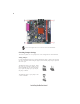
Installing Hardware
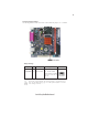
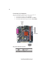
Reset Switch
Supporting the reset function requires connecting pin 5 and 7 to a momentary-contact
switch that is normally open. When the switch is closed, the board resets and runs POST.
Power Switch
Supporting the power on/off function requires connecting pins 6 and 8 to a momentary-
contact switch that is normally open. The switch should maintain contact for at least 50 ms
to signal the power supply to switch on or off. The time requirement is due to internal de-
bounce circuitry. After receiving a power on/off signal, at least two seconds elapses before
the power supply recognizes another on/off signal.
Power/Sleep/Message waiting LED
Connecting pins 2 and 4 to a single or dual-color, front panel mounted LED provides power
on/off, sleep, and message waiting indication.
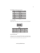
This motherboard accommodates one memory module. It can support one 240-pin DDR2
533/400 DDR2 SDRAM. The total memory capacity is 1 GB.
Do not remove any memory module from its antistatic packaging until
you are ready to install it on the motherboard. Handle the modules only
by their edges. Do not touch the components or metal parts. Always wear
a grounding strap when you handle the modules.
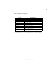
DDR2 400 200MHz
Memory module Memory Bus
DDR2 533 266MHz
DDR2 SDRAM memory module table
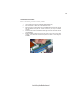
You must install one module in the slot.The module can be installed with 1 GB; total
memory capability is 1 GB.
Installing Memory Modules