
User Manual

20
Installing the Motherboard
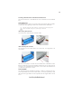
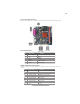
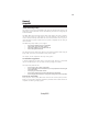
SATA1/2: Serial ATA connectors
These connectors are use to support the new Serial ATA devices for the highest date transfer
rates (1.5 Gb/s), simpler disk drive cabling and easier PC assembly. It eliminates limitations
of the current Parallel ATA interface. But maintains register compatibility and software
compatibility with Parallel ATA.
Pin Signal Name Function
1 Ground 2 TX+
3 TX- 4 Ground
5 RX- 6 RX+
7 Ground - -
Pin Signal Name
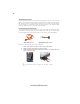
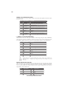
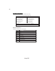
F_USB1/2: Front Panel USB headers
The motherboard has four USB ports installed on the rear edge I/O port array. Additionally,
some computer cases have USB ports at the front of the case. If you have this kind of case,
use auxiliary USB connector to connect the front-mounted ports to the motherboard.
Please make sure that the USB cable has the same pin assignment as
indicated above. A different pin assignment may cause damage or system
hang-up.
1 VCC Power
2 VCC Power
3 USBP2-N Negative data signal of
4 USBP3-N Positive data signal of
5 USBP2-P Positive data signal of
6 USBP3-P Negative data signal of
7 GND System
8 GND System
9 Key No pin
10 OC# Over current detection of
Pin Signal Name Function
Pin Signal Name
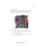
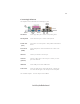
AUDIO1: Front Panel Audio header
This header allows the user to install auxiliary front-oriented microphone and line-out ports
for easier access.
1 AUD_MIC Front Panel Microphone input signal
2 AUD_GND Ground used by Analog Audio Circuits
3 AUD_MIC_BIAS Microphone Power
4 AUD_VCC Filtered +5V used by Analog Audio Circuits
5 AUD_FPOUT_R Right Channel Audio signal to Front Panel
6 AUD_RET_R Right Channel Audio signal to Return from Front Panel
7 HP_ON Reserved
8 Key No Pin
9 AUD_FPOUT_L Left Channel Audio signal to Front Panel
10 AUD_RET_L Left Channel Audio signal to Return from Front Panel
Pin Signal Name Function
Pin Signal Name