
Install v.3 Owner's manual
1
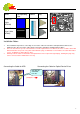
How to Read this Manual:
This manual is written specifically for people who would like to build their PCs.
A color map is to help you easily find the correct installation component and peripherals positions on the mainboard and
PC case. Those locations, connectors and jacks, are marked with a corresponding color. This allows you to identify the
correct installation locations of related parts and avoid mistakes during installation. Please refer to the following table.
No matter whether or not you are skilled in computer assembly, using the color map in this manual, you can easily
assemble a computer.
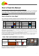
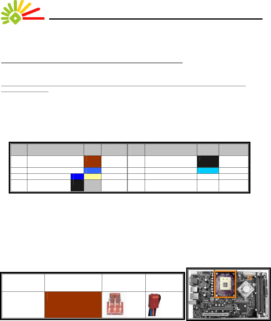
How to Read this Color Map?
This color map is not a real map but a color table that shows the component installation sequence and the corresponding
colors of the individual components. Following the sequence and matching the colors, you can easily assemble your
computer. By referring to the color table and check all colors listed to ensure all components are installed. It is easy to
identify any missing part(s) or incorrectly installed components
Sequ
ence
Names of Parts Color Completion Sequ
ence
Names of Parts Color Completion
1 Cooling Fan Power
Cord
5 External Power
Supply
2 Memory 6 Monitor
3 Hard Drive Cable 7 ATX Power W
4 Optical Device
Drive Cable
8 12V Power W
***”W”= White
There are three major columns in this table. The first column lists the component names; the second lists the colors of the
lines/connectors connecting certain components. The third is for confirmation purpose, you can check the check box after
completing the component installation.
The proper use of this table (from now, referred to as “Color Map”) provides you with a simple and mistake-free installation
process of this PC. If anything goes wrong, you can identify the problem(s) very quickly.
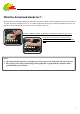
In addition, at the beginning of each section detailing each part installation, there is a color chart showing the right place for
the corresponding connectors on the mainboard and giving you an idea of what parts need to be installed and their
corresponding locations after installation.
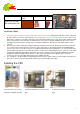
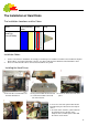
Color Chart and Installation Locations:
Name Corresponding
Color
Socket Plug
Power Line for
Cooling Fan
Also, at the beginning of each section, the locations of the installation mentioned in
that section are marked on the mainboard picture, and the colors mentioned are also listed.
Furthermore, the locations of related sockets on the mainboard are shown along with
the appearance and locations of related parts.