■ chapter 4 upgrading your computer C H A P T E R ▼ F O U R UPGRADING YOUR COMPUTER In this chapter, you will learn how to upgrade the DRAM, hard disk drive, and to install the optional wireless LAN mini PCI. Warning: We strongly recommend that you return the notebook to the dealer or the shop for the hardware upgrade. Before you perform the hardware upgrade, please turn off the system, unplug the AC adapter, remove the battery pack and also disconnect the LAN and Modem cables first for your safety.
■ chapter 4 upgrading your computer Upgrading the Hard Disk Drive Replacing the original drive with one of larger capacity can increase the hard drive capacity of your computer. The computer uses a 9.5 mm (height), 2.5-inch Ultra ATA-66 / 100 type hard disk. Be sure to make a backup copy of all your data before attempting this operation. Warning: Hard drive upgrade is a delicate process. Please observe the following instructions carefully or have a qualified technician install it for you.
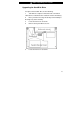
■ chapter 4 upgrading your computer Upgrading the Hard Disk Drive To replace the hard disk drive, do the following: 1. Turn OFF the computer. Unhook the AC cord and all cables/devices attached to the notebook. Remove the battery. 2. Place your hand on a large metal object momentarily to discharge any static electricity. 3. Locate and remove 6 Screw A’s. 4. Remove the System Device Cover. 5. Locate and remove 2 Screw B’s.
■ chapter 4 upgrading your computer 6. Push the HDD module to the right and separate it from the connector. Lift the module away from the bay. 7. Locate and remove 4 Screw C’s from the HDD module. Remove the metal case.
■ chapter 4 upgrading your computer 8. Re-attach the metal cover to the new hard drive and tighten 4 Screw C’s. 9. Re-attach the HDD module to the HDD connector. And re-attach 2 Screw B’s. 10. Put the System Device Cover back and re-attach 6 Screw A’s. Congratulations! You have now completed the hard drive upgrade. When you boot up the PC, you may need to create a primary HDD partition and reformat the new drive and re-install O/S, drivers, and all the necessary applications.
■ chapter 4 upgrading your computer Upgrading the System Memory Many applications will generally run faster when the computer’s dynamic memory capacity is increased. The computer provides two DDR memory sockets. There is one located underneath the System Device Cover and another one located underneath the keyboard. You can increase the amount of memory by replacing the existing one with a dual inline memory module (commonly known as SO-DIMM) of a higher capacity.
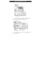
■ chapter 4 upgrading your computer Installing a memory module (DIMM) into the system To install the DIMM under the System Device Cover, do the following: 1. Power OFF the notebook. Unplug the AC cord and all cables/devices attached to the notebook. Remove the battery. 2. Place your hand on a large metal object momentarily to discharge any static electricity. Place the notebook on a flat surface and fully close the LCD lid. 3. Locate and remove 6 Screw A’s on the System Device Cover. 4.
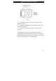
■ chapter 4 upgrading your computer 5. If you need to remove an old DIMM from the socket, press out on the latches located on both edges of the socket at the same time. The DIMM should pop up to an angle of 30 degree (see diagram below). Pull the DIMM module out of the memory socket. Store away the DIMM for the future use. 6. Install the new DIMM module into the memory socket. The DIMM will only fit in one orientation. Insert the DIMM at an angle of approximately 30 degrees into the empty memory socket.
■ chapter 4 upgrading your computer 7. Pivot the DIMM until the latches on both sides of the socket snap into place. Note: Notice the notch on the DIMM. The notches should fit nicely with the socket. 8. A’s.
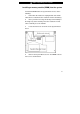
■ chapter 4 upgrading your computer To install the DIMM under the keyboard, do the following: 1. Follow Steps 1~4 from the previous section and remove Screw D. 2. Find the keyboard latches near the edges of the keyboard. The latch is spring-loaded. It will retract when pressed and revert back to its original position when released. Use a small blade to press the latch inward. The keyboard tray should pop up slightly over the latch.
■ chapter 4 upgrading your computer 3. Carefully lift up the top edge and position the keyboard out of the way and the following is revealed. 4.
■ chapter 4 upgrading your computer the same time. The DIMM should pop up to an angle of 30 degree (see diagram below). Pull the DIMM module out of the memory socket. Store away the DIMM for the future use. 5. Install the new DIMM module into the memory socket. The DIMM will only fit in one orientation. Insert the DIMM at an angle of approximately 30 degrees into the empty memory socket. Then press it firmly so that the contact edge is driven into the receiving socket. 6.
■ chapter 4 upgrading your computer 8. A’s. Put the System Device Cover back and tighten 6 Screw Congratulations! You have just completed the memory upgrade. When you boot up the computer, you should expect to see an increase in DRAM capacity. Note: Your computer has been tested with a wide range of DIMM on the market. However, not all memory modules are compatible. Check with your system vendor for a list of compatible DIMM for your computer.
■ chapter 4 upgrading your computer Adding a Mini-PCI Type Wireless LAN Card (Optional Device) Your computer comes with a unique Mini PCI Card socket, which is located next to the DRAM socket and underneath the WLAN Module Cover. The socket allows the computer to add unique features such as wireless LAN (IEEE802.11x). Ask your dealer on the availability of the mini PCI card. Warning: Installing a mini PCI card is a delicate process.
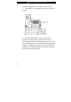
■ chapter 4 upgrading your computer Installing a Mini PCI Card into the System To install a new Mini PCI card, do the following: 1. Follow steps in the previous section, Installing a memory module (DIMM) into the system, to access the Mini PCI Socket. 2. The mini PCI card will only fit in one direction. Align the small notch in the module with the socket on the connector and insert the card at an angle of approximately 30 degrees into the empty socket.
■ chapter 4 upgrading your computer latches located on both edges of the socket at the same time. The card should pop up to an angle of 30 degree. 3. Locate 2 antenna cables with connectors. Snap the cable onto the golden connector on the Mini PCI Wireless LAN card. (Note: The connectors are fairly small! This may take some maneuvering. You may want to connect the antenna cables before inserting the wireless card into the socket. ) 4. Replace the System Device Cover and 6 Screw A’s.