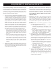
INSTALLATION INSTRUCTIONS AND OWNER’S MANUAL POWER-VENT HIGH-EFFICIENCY FIREPLACE WITH BAY WINDOW MODELS PV-28SV50-(BN,BP)-1 PV-28SV55-(CN,CP,GN,GP)-1 Power Humidifier Burners Rear Exhaust Fan Blower Mantis Front Hi Med Low ™ Installer: Leave this appliance. Consumer: Retain this reference.
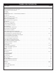
TABLE OF CONTENTS SECTION PAGE Important Safety Information ......................................................................................................................................... 3 Safety Information for Users of LP-Gas ......................................................................................................................... 4 Requirements for Massachusetts ....................................................................................................................
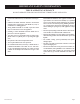
IMPORTANT SAFETY INFORMATION THIS IS A HEATING APPLIANCE DO NOT OPERATE THIS APPLIANCE WITHOUT FRONT PANEL INSTALLED. • Due to high temperatures the appliance should be located out of traffic and away from furniture and draperies. • Children and adults should be alerted to the hazards of high surface temperatures and should stay away to avoid burns or clothing ignition. • Young children should be carefully supervised when they are in the same room as the appliance.
SAFETY INFORMATION FOR USERS OF LP-GAS Propane (LP-Gas) is a flammable gas which can cause fires and explosions. In its natural state, propane is odorless and colorless. You may not know all the following safety precautions which can protect both you and your family from an accident. Read them carefully now, then review them point by point with the mem- bers of your household. Someday, there may not be a minute to lose, everyone’s safety will depend on knowing exactly what to do.
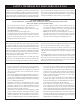
REQUIREMENTS FOR MASSACHUSETTS For all side wall horizontally vented gas fueled equipment installed in every dwelling, building or structure used in whole or in part for residential purposes, including those owned or operated by the Commonwealth and where the side wall exhaust vent termination is less than seven (7) feet above finished grade in the area of the venting, including but not limited to decks and porches, the following requirements shall be satisfied: 1. INSTALLATION OF CARBON MONOXIDE DETECTORS.
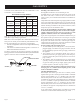
GAS SUPPLY Consult the current National Fuel Gas Code, ANSI Z223.1 CAN/ CGA-B149 (.1 or .2) installation code. Installing a New Main Gas Cock Each appliance should have its own manual gas cock. Recommended Gas Pipe Diameter Pipe Length Schedule 40 Pipe Tubing, Type L Inside Diameter Outside Diameter Nat. L.P. Nat. L.P. 0-10 feet 1/2” 3/8” 1/2” 3/8” 0-3 meters 12.7mm 9.5mm 12.7mm 9.5mm 10-40 feet 1/2” 1/2” 5/8” 1/2” 4-12 meters 12.7mm 12.7mm 15.9mm 12.7mm 40-100 feet 1/2” 1/2” 3/4” 1/2” 13-30 meters 12.
INTRODUCTION Introduction Always consult your local Building Department regarding regulations, codes or ordinances which apply to the installation of a direct vent wall furnace. Instructions to Installer 1. Installer must leave instruction manual with owner after installation. 2. Installer must have owner fill out and mail warranty card supplied with furnace. 3. Installer should show owner how to start and operate furnace and thermostat. 4.
INSTALLATION INSTRUCTIONS - GENERAL SAFETY INFORMATION 1. This installation must conform with local codes or, in the absence of local codes with NFPA54. 2. Provide adequate clearances around the product for servicing and ensure there are no obstructions to the combustion air intake situated at the back of the heater. Refer to Page 15, Figures 7 through 10. 3. The appliance must be installed on a flat, solid continuous surface (i.e. wood, metal, concrete).
CLEARANCES FOR DIRECT VENT 1. Pick a location on a wall with a clear space in the room. In selecting a location for installation, it is necessary to provide adequate accessibility clearances for servicing and proper installation. Be sure to locate the unit close enough to a 110 VAC wall receptacle to properly power appliance. 2.
CLEARANCES FOR SINGLE FLUE 1. 2. 3. Pick a location on a wall with a clear space in the room. In selecting a location for installation, it is necessary to provide adequate accessibility clearances for servicing and proper installation. Be sure to locate the unit close enough to a 115 VAC wall receptacle to properly power appliance.
SPECIFICATIONS 1 2 3 4 5 Heater with Pedestal and Single Flue Adaptor Flue Outlet 1 1/2” PVC Pipe Air Inlet Electric Cord 3/8” Flare Connection (Inside) Single Flue Adaptor Model #PVVK-SH (required) Figure 3 22618-12-0707 Page 11
SPECIFICATIONS - (continued) 1 2 3 4 5 Heater without pedestal Flue Outlet 1 1/2” PVC Pipe Air Inlet Electric Cord 3/8” Flare Connection (Inside) Single Flue Adaptor Model #PVVK-SH (required) Figure 4 Page 12 22618-12-0707
SPECIFICATIONS - (continued) Fireplace Insert with Mantel Surround with Slim Top Panel 1 Flue Outlet 1 1/2” PVC Pipe 2 Air Inlet 3 Electric Cord 4 3/8” Flare Connection (Inside) 5 Single Flue Adaptor Model #PVVK-SH (Required) 6 Surround Model #PVE-1 7 Top Cover Kit, Slim Model #PV2H Caution: Do not block louver in surround. Note: Verify fireplace opening dimensions using Figure 9, page 15.
SPECIFICATIONS - (continued) 1 2 3 4 5 6 8 Fireplace Insert with Mantel Surround with Short Top Panel Flue Outlet 1 1/2” PVC Pipe Air Inlet Electric Cord 3/8” Flare Connection (Inside) Single Flue Adaptor Model #PVVK-SH (Required) Surround Model #PVE-1 Top Cover Kit, Short Model #PV4H Caution: Do not block louver in surround. Note: Verify fireplace opening dimensions using Figure 9, page 15.
CLEARANCE TO COMBUSTIBLES Freestanding Models A B B C Figure 7 A B C D Rear Wall to Heater Side Wall to Heater Corner Installation Mantel Clearance C Figure 8 Freestanding Units 0” (2” Single Flue and 1 1/4” Direct Vent for Serviceability) 0” (4” recommended for serviceability) 0” See Figure 11 Fireplace Insert CEILING 8” 6” COMBUSTIBLE TRIM AND MANTELS ALLOWED IN SHADED AREA 40” 4” 24” 18” Single Flue Requires surround for combustion air. Do not cover surround louver.
ROUGH FRAMING DIMENSIONS A - 13 /34” MIN. CO-LINEAR 8 1/2” WHEN USING DIRECT VENTING PVVK-24H/PVVK-48H NOTE: DIMENSIONS FOR USE WITH SHORT TOP PV4H. THIS IS RECOMMENDED FOR UNIT SERVICEABILITY. B - 25 1/8” C - 28” NOTE: IF TRIM AROUND HEATER IS NECESSARY, THE SURROUND KIT PVE-1 MUST BE USED, AND SUBTRACT 1” FROM (A) DIMENSION. Figure 12 INSERT INTO MASONRY FIREPLACE A - 12 3/4” MIN. SHORT TOP PV4H 17 13/16” MIN. SLIM TOP PV2H USING PVE-1 SURROUND KIT B - 25 1/8” MIN.
WALL CLEARANCES Figure 14 22618-12-0707 Page 17
LOG SET INSTALLATION INSTRUCTIONS Log Installation The gas log set (front left log, front right log, center log and rear log) is pre-set and installed in the factory. Only the top left log and top right log are packaged separately inside the firebox for installation by the installer. 1. To access the log set parcel, lift off top panel. 2. Pivot left and right panels open. 3. Unlatch main door latches located on right and left hand side of the heater, remove door. 4.
VENT EXAMPLES FOR SINGLE FLUE Max Vent Run - 40ft. Equivalent With Three (3) 90° Elbows Special Note: The vent terminal 90° elbow and first 90° elbow off back of the heater, when within 6” (15.2cm), do not contribute to the overall vent length measurement. For each 45° elbow installed in the horizontal run, the length of the horizontal run MUST be reduced by 1.5 feet (45cm). This does not apply if the 45° elbows are installed on the vertical part of the vent system.
VENT EXAMPLES FOR SINGLE FLUE (cont.
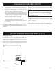
VENT EXAMPLES FOR SINGLE FLUE (cont.) Figure 22 Minimum Exterior Grade Dimension - Single Flue, Horizontal Venting Below Floor VENT CAP (SUPPLIED WITH VENT KIT) MODEL #PVVK-SV H FLASHING 12 X 2 - 45 DEG. PVC BENDS (SUPPLIED BY INSTALLER) MANTEL SURROUND MODEL #PVE-1 ROOF PITCH IS X 12 Determining Minimum Vent Height Above the Roof ROOF PITCH H (Min.
PVVK-CFA FLEX VENT KIT Available from Empire Comfort Systems, Inc. The flex vent kit is a flexible vent hose that is 42” in length. The flex vent kit will be used when installing a Mantis into an existing fireplace or any application that requires flexible pipe. The flex vent kit can be cut down, but can only be cut from one end. Do not allow sags in flexible vent pipe.
PVVK-SH HORIZONTAL VENT ADAPTOR KIT Available from Empire Comfort Systems, Inc. INSTALL FOAM GASKET FLUE ADAPTOR Attach flue adaptor to back of heater with four (4) screws. Note: No PVC cement is needed to install flue adaptor kit. PLASTIC GASKET THREADED CONNECTOR Install plastic gasket and screw threaded connector to the flue adaptor. When these connections are made, continue with your vent run. Cement all PVC joints on vent run.
HORIZONTAL EXAMPLES FOR COLINEAR DIRECT VENT Max Vent Run - 40ft. Equivalent With Three (3) 90° Elbows Special Note: The vent terminal 90° elbow and first 90° elbow off back of the heater, when within 6” (15.2cm), do not contribute to the overall vent length measurement. For each 45° elbow installed in the horizontal run, the length of the horizontal run MUST be reduced by 1.5 feet (45cm). This does not apply if the 45° elbows are installed on the vertical part of the vent system.
VERTICAL EXAMPLES FOR COLINEAR DIRECT VENT Special Note: The vent terminal (PTrap, Vent cap or two 90° elbows) and first 90° elbow off back of the heater, when within 6” (15.2cm) off back of the heater, do not contribute to the overall vent length measurement. For each 45° elbow installed in the horizontal run, the length of the horizontal run MUST be reduced by 1.5 feet (45cm). This does not apply if the 45° elbows are installed on the vertical part of the vent system.
VERTICAL EXAMPLES FOR COLINEAR DIRECT VENT Note: Exhaust must be a minimum of 3” above air intake inlet. EXHAUST TERMINATION CAP MODEL PVVTC, PTRAP OR 2 90° ELBOWS AIR INTAKE PTRAP, 2 90° ELBOWS (SUPPLIED BY INSTALLER) OR TERMINATION CAP MODEL PVVTC. PTRAP TO FACE AWAY FROM ROOF.
PVCA HORIZONTAL COLINEAR DIRECT VENT ADAPTOR Colinear adaptor to be used in conjunction with single flue horizontal vent kit PVVK-SH. The two attachments are used for colinear direct vent installation. Colinear adaptor COLINEAR ADAPTER 1. Attach colinear adaptor to back of heater with two (2) screws. 2. When adapter is connected, continue with your vent run. Cementing PVC joint is recommended, but not required on colinear fresh air intake adaptor.
PVVTC TERMINATION CAP VENT KIT Available from Empire Comfort Systems, Inc. Termination Cap PVC CEMENT Vertical exhaust cap used with 1 1/2” PVC pipe installation. Termination cap also used with colinear transition plate model PVCT. Refer to instruction manual for venting examples.
PVCT COLINEAR TRANSITION VENT KIT Available from Empire Comfort Systems, Inc. Colinear Transition Plate Note: Exhaust must be a minimum of 3” above air intake inlet. EXHAUST PTRAP OR 2 90° ELBOWS SUPPLIED BY INSTALLER OPTIONAL EXHAUST CAP MODEL PVVTC ORDER SEPARATE AIR INTAKE PTRAP OR 2 90° ELBOWS SUPPLIED BY INSTALLER AIR INTAKE PTRAP OR 2 90° ELBOWS SUPPLIED BY INSTALLER PVC CEMENT 3” MIN. PVC CEMENT 3” MIN. PVC CEMENT HEIGHT (MIN. 12”) TRANSITION PLATE PVC CEMENT HEIGHT (MIN.
DIRECT VENT INSTALLATION INSTRUCTIONS PVVK-24H and PVVK-48H Vent Kit available from Empire Comfort Systems, Inc. Note: Do not glue intake or exhaust pipes to Direct Vent Adaptor for serviceability. MANTEL SURROUND DO NOT GLUE THIS POINT EXHAUST OPENING MUST BE POINTED DOWNWARD. Figure 34 Direct Vent System Building Exterior View DIRECT VENT KIT MODEL #PVVK-24H OR PVVK-48H FLUE CENTER 12” (30.5cm) MIN. GAS SUPPLY EXTERIOR GRADE Figure 32 Horizontal Venting 45° ELBOW 47.5” (1.2m) 47.5” (1.
DIRECT VENT INSTALLATION INSTRUCTIONS (cont.) Installation on Rugs and Tile If this appliance is to be installed directly on carpeting, tile, or other combustible material, other than wood flooring, the appliance shall be installed on a metal or wood panel extending the full width and depth of the appliance. 1 1/4” (3.2cm) MIN. The base referred to above does not mean the fire-proof base as used on wood stoves.
PVVK-24H AND PVVK-48H VENT KIT Available from Empire Comfort Systems, Inc. Step 1. Install foam gasket on back side of co-axial direct vent adaptor. Step 4. Install silicone around connection between co-axial adaptor and co-axial air-inlet duct. Step 2. Attach co-axial direct vent adaptor and gasket (4 screws) to the rear of fireplace. 4 1/2” MINIMUM VENT LENGTH 3 13/16” MINIMUM TUBE LENGTH Step 5. Slide co-axial vent pipes into co-axial adaptor. Cut the PVC co-axial pipes at this time.
PVVK-24H AND PVVK-48H VENT KIT (cont.) 45° ELBOW EXHAUST OPENING MUST BE POINTED DOWNWARD. Direct Vent System Building Exterior View 47.5” (1.2m) Horizontal Venting Maximum 47.5” (1.2m) with 45° elbow. 45° elbow can be purchased from a local hardware store. 47.5” (1.2m) Maximum Horizontal Venting - 47 1/2” (1.2m) Minimum Horizontal Venting - 4” (10.
GAS CONNECTION INSTALLATION INSTRUCTIONS GAS CONNECTION (Line Supply) A 3/8” Flair gas line connection is supplied in the heater GAS SUPPLY LINE TO HEATER a. Remove top panel from heater by lifting top panel. b. Remove front and rear panel. c. Remove rubber grommet from back panel of heater and insert gas supply line through back panel of heater. d. Connect gas supply line to flexible gas hose. Ensure that flexible gas hose is not kinked after fitting gas supply line. e.
OPERATING INSTRUCTIONS CHECKLIST BEFORE OPERATING THIS APPLIANCE, CAREFULLY PROCEED THROUGH THE FOLLOWING CHECKLIST 1. Read and understand these instructions before installing or operating this appliance. 2. This appliance is should be installed and repaired by a fully qualified service person who must be familiar with the installation of the Mantis Power-Vent High-Efficiency Fireplace. 3. Installers who are not familiar with the installation of this appliance should contact Empire Comfort Systems, Inc.
LIGHTING INSTRUCTIONS 1. Main Electrical power supply must always be switched on to the unit with the two burner switches in the off position (up) before lighting the heater. 2. Turn on main gas supply. 3. Verify that main electrical supply is switched on by checking the 115V AC power status display (Figures 40 and 41) indicator is on. 4. Burner selection: select low burn (front burner), medium burn (rear burner), or high burn (both burners).
LIGHTING INSTRUCTIONS FOR YOUR SAFETY READ BEFORE LIGHTING WARNING: IF YOU DO NOT FOLLOW THESE INSTRUCTIONS EXACTLY, A FIRE OR EXPLOSION MAY RESULT CAUSING PROPERTY DAMAGE, PERSONAL INJURY, OR LOSS OF LIFE. A. BEFORE LIGHTING smell all around the appliance area for gas. Be sure to smell next to the floor because some gas is heavier than air and will settle on the floor. WHAT TO DO IF YOU SMELL GAS • Do not try to light any appliance. • Do not touch any electrical switch.
FAN OPERATION The 3-speed main convection fan will automatically start approximately 3 to 5 minutes after the heater has warmed up. Note: The 3-speed main convection fan is automatically controlled and will operate on three preset speeds. Depending on your burner setting and the surrounding ambient temperature, the L.E.D lights (Page 36, Figure 43) for the fan will light up. The bottom L.E.D light (Figure 43F) is low speed setting, and middle L.E.
GAS CONVERSION INSTRUCTIONS Warning: Conversion must be done by a qualified service technician. Main burner orifices, front burner bushing, and gas conversion label are provided in conversion kit attached to manifold pipe. CONVERSION INSTRUCTIONS FROM (LP) PROPANE GAS TO NATURAL GAS 1. 2. 3. 4. 5. Turn OFF gas supply and electrical power to fireplace. Remove lower front panel. Unscrew regulator stem from gas valve and reverse regulator stem to the natural gas position and screw stem back into gas valve.
GAS CONVERSION INSTRUCTIONS Warning: Conversion must be done by a qualified service technician. Main burner orifice(s) and new gas conversion label are provided in conversion kit attached to manifold pipe. CONVERSION INSTRUCTIONS FROM NATURAL GAS TO (LP) PROPANE GAS 1. 2. 3. 4. 5. Turn OFF gas supply and electrical power to fireplace. Remove lower front panel. Unscrew regulator stem from gas valve and reverse regulator stem to the propane gas position and screw stem back into gas valve.
AUTOMATIC HUMIDIFIER OPERATION Most gas heaters dry out the air in the room. The Mantis has ingeniously solved this problem with an Automatic Humidifier. Gas contains moisture which is normally expelled out the flue or chimney after combustion. But the Mantis is so efficient by taking 92% of the heat out of the burnt gases that the moisture drops out and condenses in the back of the heater.
OPTIONAL CONTROLLERS MODELS FRBTP FRBTC Battery Operated Remote w/ Programmable Thermostat Battery Operated Remote w/ Thermostat TRW TMV2 Battery Operated Wireless Remote Wall Thermostat Thermostat, 2 Stage See your Mantis dealer for correct controller type.
OPTIONAL CONTROLLERS R: 24 Volt Hot W1: Heat Relay Stage 1 (Front burner) W2: Heat Relay Stage 2 (Rear burner) C: 24 Volt Common BLUE TO THERMOSTAT R W1 JUMPER WIRE (TO BE REMOVED) W2 C JUNCTION BLOCK C W2 W1 R BLUE RED BLACK WHITE BLUE TO TRANSFORMER TO “T1” (FRONT BURNER) TO “T2” (REAR BURNER) TO “T1” TO “T2” Figure 51 Replace front louver panel and plug unit into outlet. Turn both burner switches to ON position. Burner switches must remain in the ON position for thermostat to function.
WIRING The appliance, when installed, must be electrically grounded in accordance with local codes or, in the absence of local codes, with the National Electrical Code, ANSI/NFPA 70 or Canadian Electrical Code, CSA C22.1, if an external electrical source is utilized. This appliance is equipped with a three-prong [grounding] plug for your protection against shock hazard and should be plugged directly into a properly grounded three-prong receptacle. Do not cut or remove the grounding prong from this plug.
GENERAL INFORMATION Over Temperature Cut Out The Mantis Power-Vent High-Efficiency Fireplace is protected against overheating with a high temperature 80°C (176°F) cut off switch to protect the heat exchanger, plastic sump and flue fan. The high temperature cut off switch will automatically switch off the gas supply to the heater, if the temperature in the room where the heater is located reaches approximately 28°C (82.4°F). The heater will go into lock out mode.
MAINTENANCE 6. 7. 8. 9. 10. 11. 12. 13. 14. Insert a putty knife between glass and bottom corners on frame. Carefully separate glass from frame. Use putty knife to remove silicone and gasket material from frame. Surface of frame must be clean and dry. At each corner of frame apply two (2) three inch beads of high temperate (orange) silicone. With thin gasket on glass facing silicone on frame, insert glass into frame. Carefully press the glass onto frame in order to have contact between glass and silicone.
UNIT OPERATING FAULTS SERVICE AND INSTALLATION OF THE APPLIANCE SHOULD BE CARRIED OUT BY AUTHORIZED PERSONNEL ONLY. THE MAJOR CAUSE OF OPERATING PROBLEMS WITH GAS FIREPLACE HEATERS IS IMPROPER GAS PRESSURE, INCORRECT LOG PLACEMENT, IMPROPER INSTALLATION, INCORRECT FLUE INSTALLATION, INCORRECT SWITCHING OF BURNERS, DIPS/SPIKES IN THE INCOMING POWER OR REVERSE POLARITIES.
MAIN CONVECTION FAN The main convection fan in the heater should be checked, serviced and cleaned annually by a qualified service person to ensure that your appliance is operating efficiently. Note: If the main convection fan becomes clogged with lint and dust an over-temperature situation will occur through the heater exchange system and the over-temperature safety switch will stop the heater from operating. HEAT EXCHANGER The heat exchanger of the unit is located at the rear of the heater.
PEDESTAL INSTALLATION INSTRUCTIONS Optional Pedestal Assembly Installation 1. Remove pedestal assembly from carton. Handle pedestal with care to avoid paint damage. 2. Place pedestal assembly into position where heater is to be located. 3. Lift and place main body of heater on top of pedestal assembly and align main body of heater with locating tabs provided on pedestal assembly (refer to diagram).
PARTS LIST PLEASE NOTE: When ordering parts, it is very important that part number and description of part coincide.
PARTS LIST PLEASE NOTE: When ordering parts, it is very important that part number and description of part coincide.
PARTS VIEW 1 2 3 4 8 9 10 9 5 5 6 16 11 15 12 18 9 14 17 13 33 7 19 30 28 27 22 31 29 24 20 28 26 25 29 32 34 36 35 21 Page 52 23 22618-12-0707
PARTS VIEW 37 38 39 51 58 59 47 48 49 53 58 57 56 55 52 45 42 54 43 44 46 47 48 40 41 50 53 74 73 68 72 69 75 70 71 76 62 60 61 63 66 65 77 79 78 81 67 64 85 82 80 86 84 87 83 88 91 92 89 22618-12-0707 90 Page 53
WARRANTY TERMS Purchase Date: Dealer Name/Phone: Installer - Place Serial Number Sticker Here and Leave this Manual with the Consumer. Limited Ten-Year Heat Exchanger Warranty Empire promises to the owner that if the heat exchanger (see parts list) fails because of defective workmanship or material within ten years from the date of purchase, Empire will repair, or at Empire’s option, replace the defective heat exchanger.
HOW TO ORDER REPAIR PARTS Parts can be ordered only through your service person or dealer. For best results, the service person or dealer should order parts through the distributor. Parts can be shipped directly to the service person/dealer. All parts listed in the Parts List have a Part Number. When ordering parts, first obtain the Model Number from the name plate on your equipment.
SERVICE NOTES Mantis is a trademark of: Empire Comfort Systems, Inc. 918 Freeburg Ave. Belleville, IL 62220 PH: 618-233-7420 or 800-851-3153 FAX: 618-233-7097 or 800-443-8648 info@empirecomfort.com www.empirecomfort.