i Preface Copyright This publication, including all photographs, illustrations and software, is protected under international copyright laws, with all rights reserved. Neither this manual, nor any of the material contained herein, may be reproduced without written consent of the author. Version 1.0 Disclaimer The information in this document is subject to change without notice.
ii Declaration of Conformity This device complies with part 15 of the FCC rules. Operation is subject to the following conditions: • • This device may not cause harmful interference, and This device must accept any interference received, including interference that may cause undesired operation Canadian Department of Communications This class B digital apparatus meets all requirements of the Canadian Interferencecausing Equipment Regulations.
iii Safety Instructions Your system is designed and tested to meet the latest standards of safety for information technology equipment. However, to ensure your safety, it is important that you read the following safety instructions. Setting up your system • • • • • • Read and follow all instructions in the documentation before you operate your system. Do not use this product near water or a heated source such as a radiator. Set up the system on a stable surface.
iv Safety cautions and warnings Optical Drive Satety Information Optical drive sold with this system contains a CLASS 1 LASER PRODUCT. CAUTION: Invisible laser radiation when open. Do not stare into beam or view directly with optical instructions. WARNING: Makeing adjustments or performing procedures other than those specified in the user’s manual may result in hazardous laser exposuer. Do not attempt to disassemble the optical drive.
v TABLE OF CONTENTS Preface i Chapter 1 1 Introducing the PC 1 Introduction......................................................................................1 Specification......................................................................................2 Front and Rear I/O............................................................................3 Packing Contents..............................................................................
vi Chapter 4 25 Using the Software 25 About the Software DVD-ROM/CD-ROM.................................25 Auto-installing under Windows 7...............................................25 Running Setup....................................................................26 Manual Installation........................................................................28 Utility Software Reference............................................................
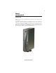
1 Chapter 1 Introducing the PC Introducting Thank you for choosing 3.8L MS200 of great performance and with stylish and flexible design. Support Intel® Socket LGA1156 Core i3/i5 Clarkdale processors and a dimension of 270mm (H)* 205mm (D)* 70mm (W), 3.8L SFF provides the features of low power consumption (working with a 120Watt power adaptor), low noise (<30db) and space saving. The chipset is Intel® H55, supporting up to 8 GB of system memory with DDR3 memory SO-DIMM, 3.
2 Specification Chipset • Intel® H55 CPU Support • Socket LGA1156 for Intel® Core i3/i5 Clarkdale processors (up to 73W) Memory • 2 x SO-DIMM up to 8 GB Graphics Storage • • Built-in Intel® HD graphics Supported 1 x 3.5” SATA II HDD ODD • Support Slim DVD Super-multi Tray type Front Panel • • • • 4 x USB2.
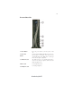
3 Front and Rear I/O 1. Power Button Press the prower button to turn the system on and off. 2. 4 IN 1 Card Reader Supports SD Card/ MMC Card/ MS Card. You can easily read phone or other files on the momery card. Your digital cameras, DVs, MP3 players or other digital devices are highly compatible. 3. USB Connectors The USB connectors is for attaching USB devices, such as mouse, keyboard, printer, scanner and other USB-compatible device. 4. Mic In Jack Connecting Microphone. 5.
4 6. HDMI Connector Connecting HDMI Device. 7. USB Connectors Connecting USB Devices (USB2.0 Ports) 8. Eight channel HD Audio Microphone Jack/ Headphone Jack/ Line In Jack. 9. DC Jack It is used for power adapter 10. Antenna It is used for an optional antenna 11. D-SUB Connector Connecting VGA Monitor. 12. LAN Connecting the Network. 13. TV Tuner (optional) TV in jack.
5 Packing Contents Driver DVD Manual Stand Power NOTE: Please contact us immediately if any of the items is damaged or missing.
6 Memo Introducing the PC
7 Chapter 2 Installing the PC System Quick Installation 1. Connecting HDMI device. 2. Connecting VGA Monitor. (D-SUB Connector) 3. The USB connectors is for attaching USB devices, such as mouse, keyboard, printer, scanner and other USB-compatible device.
8 4. Connecting the Network. (LAN Connector) 5. Connecting the Microphone. (Microphone Jack) 6. Connecting Speakers or Headphones. (Headphone Jack) 7. Connecting External Audio Device.
9 8. Connecting Power.
10 Memo Installing the PC
11 Chapter 3 Using BIOS About the Setup Utility The computer uses the latest “American Megatrends Inc. ” BIOS with support for Windows Plug and Play. The CMOS chip on the motherboard contains the ROM setup instructions for configuring the motherboard BIOS. The BIOS (Basic Input and Output System) Setup Utility displays the system’s configuration status and provides you with options to set system parameters.
12 Press the delete key to access the BIOS Setup Utility. CMOS Setup Utility - Copyright (C) 1985-2010, American Megatrends, Inc.
13 For the purpose of better product maintenance, we reserve the right to change the BIOS items presented in the manual. The BIOS setup screens shown in this chapter are for reference only. Please visit our website for updated manual. Standard CMOS Setup This option displays basic information about your system. CMOS Setup Utility - Copyright (C) 1985-2010, American Megatrends, Inc.
14 Type (Auto) Use this item to configure the type of the IDE device that you specify. If the feature is enabled, it will enhance hard disk performance by reading or writing more data during each transfer. PIO Mode (Auto) Use this item to set the PIO mode to enhance hard disk performance by optimizing the hard disk timing. DMA Mode (Auto) DMA capability allows users to improve the transfer-speed and data-integrity for compatible IDE devices. Press to return to the Standard CMOS Setup page.
15 Advanced Setup This page sets up more advanced information about your system. Handle this page with caution. Any changes can affect the operation of your computer. CMOS Setup Utility - Copyright (C) 1985-2010, American Megatrends, Inc.
16 fOptical Disk Driver Priority (Press Enter) Scroll to this item and press to view the following screen: CMOS Setup Utility - Copyright (C) 1985-2010, American Megatrends, Inc. Optical Disk Driver Priority Help Item Optical Disk Driver 1st Drive CD/DVD: PM-Optiarc D mnlk : Move Enter : Select F1: General Help Specifies the boot sequence from the available devices. +/-/: Value F10: Save ESC: Exit F9: Optimized Defaults Press to return to the Advanced BIOS Features page.
17 Advanced Chipset Setup This page sets up more advanced information about your system. Handle this page with caution. Any changes can affect the operation of your computer. CMOS Setup Utility - Copyright (C) 1985-2010, American Megatrends, Inc. Advanced Chipset Setup Intel EIST Intel XD Bit Intel VT Memory Hole Remapping Video Memory Size DVMT Mode DVMT/Fixed Memory Size Enabled Enabled Enabled Enabled 32MB DVMT Mode 256MB Help Item When disabled, force the XD feature flag to always return to 0.
18 Integrated Peripherals This page sets up some parameters for peripheral devices connected to the system. CMOS Setup Utility - Copyright (C) 1985-2010, American Megatrends, Inc.
19 Power Management Setup This page sets up some parameters for system power management operation. CMOS Setup Utility - Copyright (C) 1985-2010, American Megatrends, Inc. Power Management Setup ACPI Aware O/S Suspend mode Deep Power Off Mode Power On by RTC Alarm Power On by PCIE Devices Wake Up by USB KB/Mouse Restore On AC Power Loss Yes S3 (STR) Enabled Disabled Disabled Enabled Last State Help Item Enable/Disable ACPI support for Operating System.
20 PC Health Status On motherboards support hardware monitoring, this item lets you monitor the parameters for critical voltages, temperatures and fan speeds. CMOS Setup Utility - Copyright (C) 1985-2010, American Megatrends, Inc. PC Health Status Help Item CPU Temperature (PECI Mode) : System Temperature : CPU Fan1 Speed : CPU Fan2 Speed : CPU Core : + 3.30V : + 5.00 V : +12.0 V : 5VSB : VBAT : 43 42°C/107°F 1066 RPM 1146 RPM 1.120 V 3.296 V 5.053 V 12.032 V 5.026 V 3.
21 System Component Characteristics These items display the monitoring of the overall inboard hardware health events, such as System & CPU temperature, CPU & DIMM voltage, CPU & system fan speed,...etc. • • • • • • • • • • CPU Temperature (PECI Mode) System Temperature CPU Fan1 Speed CPU Fan2 Speed CPU Core + 3.30V + 5.00V + 12.00V 5VSB VBAT Shutdown Temperature (Disabled) Enable you to set the maximum temperature the system can reach before powering down.
22 Enable Clock to All PCI/PCIE (Disabled) This item displays the information of current manufacturer of the CPU installed in your computer. Ratio Actual Value: 12 This item shows the actual ratio of the CPU installed in your system. CPU Frequency Setting (533MHz) This item is used to set the CPU Frequency. CPU Spread Spectrum (Disabled) If you enable spread spectrum, it can significantly reduce the EMI (Electro-Magnetic Interference) generated by the system.
23 Change User Password (Press Enter) You can select this option and press to access the sub menu. You can use the submenu to change the user password. Security Check (Setup) This item is set to enable or disable the security check. Load Default Settings This option opens a dialog box that lets you install stability-oriented defaults for all appropriate items in the Setup Utility. Select and then press to install the defaults.
24 Memo Using BIOS
25 Chapter 4 Using the Software About the Software DVD-ROM/CD-ROM The support software DVD-ROM/CD-ROM that is included in the motherboard package contains all the drivers and utility programs needed to properly run the bundled products. Below you can find a brief description of each software program, and the location for your motherboard version. More information on some programs is available in a README file, located in the same directory as the software.
26 Drivers Tab Setup Click the Setup button to run the software installation program. Select from the menu which software you want to install. Browse CD The Browse CD button is the standard Windows command that allows you to open Windows Explorer and show the contents of the support disk. Before installing the software from Windows Explorer, look for a file named README.TXT or something similar. This file may contain important information to help you install the software correctly.
27 2. Click Next. The following screen appears: 3. Check the box next to the items you want to install. The default options are recommended. 4. Click Next run the Installation Wizard. An item installation screen appears: 5. Follow the instructions on the screen to install the items. Drivers and software are automatically installed in sequence. Follow the onscreen instructions, confirm commands and allow the computer to restart a few times to complete the installation.
28 Windows 7 will appear below UAC (User Account Control) message after the system restart. You must select “Allow” to install the next driver. Continue this process to complete the drivers installation. Manual Installation Insert the disk in the DVD-ROM/CD-ROM drive and locate the PATH.DOC file in the root directory. This file contains the information needed to locate the drivers for your motherboard.
29 Chapter 5 Trouble Shooting Start up problems during assembly After assembling the PC for the first time you may experience some start up problems. Before calling for technical support or returning for warranty, this chapter may help to address some of the common questions using some basic troubleshooting tips. a) System does not power up and the fans are not running. 1.Disassemble the PC to remove the VGA adaptor card, DDR memory, LAN, USB and other peripherals including keyboard and mouse.
30 c) The PC suddenly shuts down while booting up. 1. The CPU may experience overheating so it will shutdown to protect itself. Ensure the CPU fan is working properly. 2. From the BIOS setting, try to disable the Smartfan function to let the fan run at default speed. Doing a Load Optimised Default will also disable the Smartfan. Start up problems after prolong use After a prolong period of use your PC may experience start up problems again.
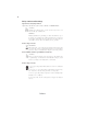
If fail, contact RMA CLR CMOS and restart. Yes Halt at POST screen? Yes Check if monitor has display Yes Check if Power Supply Unit (PSU) is working Power Bu on is pressed but PC fails to start. CMOS setup error, - need to CLRCMOS. HDD problem.
32 Memo Trouble Shooting