
Installation Instructions


754764-100 Rev. D
5
INSTALLATION AND FRAMING INSTRUCTIONS
The variety of installations possible for this whirlpool may require framing procedures other than those shown. Locate studs as
needed. Ensure roughing-in dimensions are proper, plumb and square. Provisions must be made in all installations for an access
opening for servicing the pump and controls. It is strongly recommended that an additional opening be provided for access to the
drain components. The apron should not be used as the primary access opening.
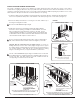
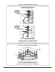
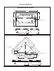
TYPICAL PIER TYPE INSTALLATION
AS DESIRED
F
CUTOUT
AS DESIRED
G
CUTOUT
C
24
(610 mm)
12
(305 mm)
MOUNTING
SURFACE
WATERPROOF
SEALANT
BATH
TYPICAL RECESS INSTALLATION
24
(610 mm)
12
(305 mm)
C
E
D
W
LEVELING
STRINGERS
TILE
TILE BEAD
STRIP
LEVELING STRINGER
1 x 4 (not for support)
BATH
ADHESIVE
SEALANT
WALLBOARD
NOTE: Tile bead kit not included and
must be purchased separately.
C*
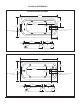
TYPICAL INSTALLATION
FIGURE 1
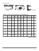
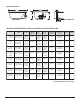
3. Install drain components to the whirlpool following the drain installation
instructions. Before replacing your whirlpool for final installation, be certain
that an opening has been provided in the sub-floor for the drain. See the
roughing-in drawing and Ta ble 1 for suggested opening size (shadowed) and
location dimensions. The drain/overflow of the bath extends below the bottom
of the bath. Note that this requires a cutout in the floor.
The floor structure beneath the bath must be able to support a total weight of
bath, water, and bather. Refer to Ta ble 1 under total weight for your model.
2. Remove the whirlpool and attach a 1 x 4 stringer to the studs, with the top of
the stringer touching the traced line.
The rim of the bath must not support weight.
1. Position the whirlpool into the installation opening and level the deck in both directions, shimming the integral leveling
feet IF necessary. Mark the final position of the underside of the deck by tracing a line on to the studs (see Figure 1).
!
!
ACCESS PANEL MUST BE LOCATED
ON THE SAME SIDE AS THE MOTOR.
ALLOW OPEN FRAMING ON PUMP/MOTOR
END FOR SERVICE.
ACCESS PANEL MUST BE LOCATED
ON THE SAME SIDE AS THE MOTOR.
ALLOW OPEN FRAMING ON
PUMP/MOTOR END FOR SERVICE.
FOR E & D DIMENSIONS SEE TABLE 1 ON PAGE 7 - 8.
FOR C, G & F DIMENSIONS SEE TABLE 1 ON PAGE 7 - 8.
NOTE:
FRONT EDGE
OF BATH MUST
BE SUPPORTED
BY STUD WALL OR
ELJER APRON KIT
UNLESS AN ACCESS OPENING OF AT LEAST 12" X 24" (305 X 610mm)
IS PROVIDED, WARRANTY SERVICE WILL NOT BE PERFORMED.
UNLESS AN ACCESS OPENING OF AT LEAST 12" X 24" (305 X 610mm)
IS PROVIDED, WARRANTY SERVICE WILL NOT BE PERFORMED.
ACCESS PANELS NOT REQUIRED
FOR BATH TUBS.
ACCESS PANELS NOT REQUIRED
FOR BATH TUBS.
SEE TABLE 1 ON PAGE 7 - 8.
The bath must be supported along it’s entire bottom. Use mortar as
bedding material (do not use sand or foam). Apply enough mortar to support
the complete bottom of the bath. After the mortar has been poured, and before it
sets, position whirlpool or bath until the rim is leveled against the leveling
stringers or mounting surfaces (see “Typical Installations”) shown below.
!
The rim of the bath must not support weight. If foundation base is used, allow
the bedding material to completely harden before applying weight to the rim or
bottom of the bath. Any finish material such as tile or wall board must be
self-supporting if it contacts the deck of the bath.