
User's Manual


M1 Installation and Programming Manual
Page 47
Menu 14 - Wireless Definitions
WirelessDefinitions Description
The Wireless Definitions menu is broken into four parts: 1:Receiver Options, 2:Xmitter
Options, 3:Xmitter Enroll, and 4:Keyfob Event Definitions. To program Receiver Options
press the right arrow key. To move to Transmitter Options, Xmitter Enroll, or Keyfob
Event Definitions press the up or down arrow keys.
R01: Receiver Size. Identifies the size of the connected Receiver so the appropriate
number of zones may be reserved. For the NX408E 8 zone receiver enter a 0, for a
NX416E 16 zone receiver enter a 1, for a NX448E 48 zone receiver enter a 2. The M1
will know these zones are wireless, starting from the ZnBank setting in the next option.
R02:ZnBank Starting Zone. Identifies where the first wireless zone begins. Using the
receiver size setting and this starting number, the M1 blocks out the required number of
zones. If another zone expander (hardwired) is encountered that results in a duplicate
zone, the M1 will error tone and return to a 00 setting. To resolve the conflict: move the
starting zone to another setting, move the conflicting zone expander to another address,
or reduce the receiver size setting. Valid starting zones must be increments of 16:
Example: Entering a value of 2 for receiver size and 02 for starting zone would block out
48 zones from 17 thru 64 as wireless. NOTE: If an 8 zone receiver is installed, the upper
8 zones are not available (wasted) as far as the control is concerned. Receivers with
multiples of 16 zones (NX416E and NX448E) are therefore better economic choices.
R03: Reg. Supervision sets the interval, in hours, for “check-in” by transmitters which are
programmed for “Supervision Type 1”, see transmitter option 01. Valid range is 001 to
255 hours, however a value lower than 4 is not recommended. Default value is 24.
R04: Fire Supervision sets the interval, in hours, for “check-in” by transmitters which are
programmed for “Supervision Type 2” (Fire), see transmitter option 02. Valid range is 001
to 255 hours, however a value lower than 4 is not recommended. Default value is 004.
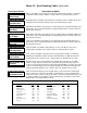
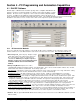
1:Rec Selb Prgr
Receiver Options
RO2:=00 ZnBank r
StartingZone xxx
RO3:=24 Hours r
Reg. Supervision
RO4:=004 Hours r
Fire Supervision
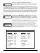
Press RIGHT arrow key to select this menu. Press UP or DOWN arrow keys to select
another menu. The ELK key backs up one menu level. To exit press the * or Exit key.
14-Wireless
Definitions r
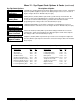
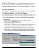
Requires
ELK-W035A
Wiring Assembly
Caddx Brand Receiver Board
+
White (n/a)
Brown (n/a)
B
A
NEG
C
J3 J4
1 WAY
X-10
2 WAY
JP2
RS232
+
R1
TIP
RING
T1
AUX
+12V
X-10
M1 PCB
Connect
to J3
-
A Data
Green
Red
Black
NX-408E
NX-416E
NX-448E
SET ALL FOUR ADDRESS
SWITCHES TO OFF!
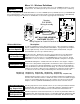
Wiring Diagram for Caddx NX Receiver to ELK-M1
The M1 is compatible with the Caddx brand wireless receivers: NX408E (8 zones), NX416E (16 zones), and NX448E (48
zones) and transmitters. Only 1 Receiver may be connected to the M1. A special 5 pin wiring harness (ELK-WO35A)
is required and it plugs into connector J3 “Aux Data Bus” located on the upper right side of the board.
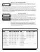
RO1:=0 Rec Sizer
0=8 ZoneReceiver
02=(Zone 17) 04=(Zone 33) 06=(Zone 49) 08=(Zone 65) 10=(Zone 81)
12=(Zone 97) 14=(Zone 113) 16=(Zone 129) 18=(Zone 145) 20=(Zone 161) 22=(Zone 177)