
Data Sheet
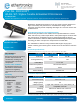


2.4 / 5 GHz Ethertronics’ PCB Embedded Antenna Specifications
Ethertronics produces a wide variety of standard and custom antennas to meet user needs.
© 2020 Ethertronics
tel +(1) 858.550.3820 | fax +(1) 858.550.3821
email: eth.info@avx.com
5501 Oberlin Drive, Suite 100 San Diego, CA 92121 - USA
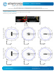
Antenna Tuning Options
Typical Performance using 100 mm cable tested on PC-ABS
MODE T1 T2 T3 T4
PADS Connect: P2 Connect: P1 Connect: P2+P3 Connect: P1+P3
Outcome:
(Ref: Baseline)
~200 MHz
shift low
~250 MHz
shift low
~350 MHz
shift low
~370 MHz
shift low
Options for Tuning: "2.4GHz (Lower)"
Options for Tuning: "2.4GHz (Higher)"
MODE C1 C2
PADS Cut: C1 Cut: C2
Outcome:
(Ref: Baseline)
~170 MHz
shift high
~300 MHz
shift high
Options for Tuning: "5GHz (Lower)"
MODE T5 T6 T7 T8
PADS
Connect: P4
Connect: P4+P5
Connect: P6 Connect: P5+P6
Outcome:
(Ref: Baseline)
~200 MHz
shift low
~1500 MHz
shift low
~500 MHz
shift low
~1900 MHz
shift low
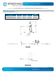
*This antenna has unique features enabling limited range RF tuning by leaving P1 - P6 and C1 - C2 connected
by “solder bridge” or disconnected with a “cut” to the trace. Refer to detailed tuning options below.
Ref: Baseline = Typical Performance using 100 mm cable tested on PC-ABS
DATASHEET | Part No. 1001932PT
C2 C1
P1
P2
P3
P6
P5
P4