
User Instructions

APPLICATION
The ELK-6022 Sensor is compatible with Wireless Receivers
and Controls that accept Elk’s ‘RFTW’ two-way technology;
such as, the ELK-M1XRFTW. The 6022 is capable of securing
up to 3 doors or windows. It has 1 built-in reed switch plus 2
external closed circuit zone inputs (IN1 & IN3). When the 6022
transmits to the receiver it sends a unique TXID identifier and a
Loop number belonging to each input zone. The Loop number
is used by the Control to determine which input is assigned to
which wireless zone.
The 6022 features Elk’s Industry Leading Two-Way Technology,
capable of on-demand status updates as well as extended
range and extremely long battery life.
SPECIFICATIONS:
Frequency: 902 Mhz - 928 Mhz frequency hopping
Zones: Built-in Reed, IN1, and IN3 (Closed circuit terminals)
Tamper: Front and back provided by a single flex plunger
Dimensions: 1.5”W x 3”L x .9”D Mag: .57”W x 1.5L x .6D
Maximum Operating Gap of Reed: 1/2”
Operating Temperature: 32° to 120° F (0° to 49° Degrees C)
Relative Humidity: 5-95% Non-Condensing
Battery: 3V Lithium - See Battery Installation & Replacement
Unique TXID Code: Over 1 million combinations
Enrolling from M1 Keypad Installer Programming
1. Enter M1 Keypad Installer Programming and scroll or
navigate to Menu: 14-Wireless Setup
2. Press right arrow and scroll up to Sub-Menu: 3:Learn Sel
3. Press right arrow and pick a WZone (wireless zone) number.
4. Press right arrow to Lrn (Enroll) a new sensor.
5. Insert the Battery into the 6022 as soon as the keypad
displays Push Transmitter Button. Elk’s RFTW sensors
utilize a unique battery insertion signal for enrollment.
NOTE: If battery happens to be already inserted, remove
it and wait 5 seconds before re-inserting.
6. If enrollment is successful the M1 Keypad will ding-dong
and briefly display the 6 digit TXID code attached to the
sensor. For Dr/Wnd sensors the 1st digit is “A” followed by
5 digits (0 to F). e.g. A9AB4C. If enrollment fails and a
TXID does not display; remove the battery, wait 5 seconds,
then re-insert. It may be necessary to repeat steps 3 - 6.
To use the 2nd or 3rd zone of the 6022 each must be enrolled
separately as another M1 Wireless Zone. We suggest they
be enrolled in sequence with the 1st zone. See Step 7.
7. The M1 Rapid-Enroll feature advances to the next zone in
sequence and waits for a battery insert signal. Just repeat
step 5 for each additional wireless sensor. The M1G voice
will speak; “Press Transmitter button for zone xx” (next zone).
To use the 2nd Zone (IN1) of the 6022, enroll it again as the
next wireless zone in sequence by removing the battery,
waiting 10 seconds, and re-inserting. The 6022 will be
enrolled again as the next sequential wireless zone. Repeat
if using the 3rd zone of the 6022.
8. To end Rapid-Enroll press the ELK key one time AFTER all
wireless zones (sensors) have been enrolled.
9.
Set the Loop Number - VERY IMPORTANT for the 6022.
Scroll up or down to the desired M1 wireless zone and press
the left arrow. The screen will display a 9 digit number (the
TXID in decimal) followed by Loop=. Press the right arrow
and move cursor over to Loop=. Set the Loop to 1, 2, or 3
depending on the input of the 6022 being used for this
particular wireless zone. Loop 2 is for the built-in reed, Loop
1 is for external IN1, and Loop 3 is for external IN3.
ELK-6022 Wireless Universal 3-Zone Door/Window Sensor
Battery Installation and Replacement
A Low Battery signal will be reported to the Control when the
sensor battery needs to be replaced.
1. Remove sensor cover by grasping the sides and
inserting the tip of a small flat screwdriver in the end slot.
2. Observe correct polarity when installing the new battery
(see Fig 2). Be careful to not bend or damage the metal
contact leafs holding the battery.
Approved Batteries: 3V Lithium - Panasonic CR123A,
Duracell DL123A, Varta CR123A, Sanyo CR123A
3. Test sensor operation with panel.
Operational Testing
A two color LED is functional for 10 minutes after installation of
the Battery. The LED may be re-activated for service or
diagnostics by removing and reinstalling the battery, OR by
activating the Walk Test Area menu on the M1 Keypad. NOTE:
The LED may be difficult to see under direct sunlight.
GOOD = GREEN blink This indicates Sensor transmitted a
signal and was received and acknowledged by the Receiver.
CAUTION = RED blink(s) following by a GREEN This
indicates Sensor is experience difficulty reaching the
Receiver. The first RED occurs after sensor has failed 4
times. Each additional RED blink indicates another attempt
(up to 16) to reach the receiver. After a 16 failed attempts
the sensor will timeout and go idle for 5 minutes. A GREEN
blink anytime prior to 16 attempts indicates sensor was finally
successful. During each check-in request or supervisory
check-in interval the sensor will update or report the current
state of it’s input to the receiver.
BAD = RED blinks with no GREEN This may indicate that
either: Receiver and Sensor are out of range, Receiver is
not working, or Sensor is not transmitting.
* The two color LED will remain active throughout the Walk
Test process OR for 10 minutes after battery insertion and the
enrollment has ended.
A complete system test and Walk Test of all wireless zones
using the prescribed M1 Keypad Menu 3 - Walktest Area
feature should be performed a least once a year.
Printed In USA
12/1/2011
Front Page
WARNING! Do not reverse polarity of the battery!
PO Box 100 3266 US Hwy 70 West
Hildebran, NC 28637
Ph 828-397-4200 Fax 828-397-4415 http://www.elkproducts.com
+ -
Press the ELK key twice to return to the Zone select display.
Scroll to each of the other wireless zones and set or verify
their Loop number. NOTE: A sensor will not operate if
the Loop number is not set correctly. Loop=2 is always
the setting for the built-in reed input.
IMPORTANT! Once all wireless zones have been enrolled the
next step is to exit Menu 14 and proceed to Menu: 5 - Zone
Definitions to program their name, zone type, and options.
Enrolling from ElkRP Software
1. Launch ElkRP and open the desired Customer Account file.
2. RP requires wireless zones to be defined in groups of 16.
Wireless can begin at Zone 17 (Group 2) but CANNOT go
beyond Zone 160 (Group 10). In the Folders column right
click on > Zones (Inputs) to create a group of 16 wireless
zones. Then click New Wireless Zones. Place a check
mark in the box beside the desired group, then click OK.
Repeat if additional wireless groups are required.
NOTE: Only Zones 17 to 160 can be used for wireless
zones (max. of 144 wireless sensors). If a large number
of wireless zones are expected, AVOID conflict with
existing or future Hardwired Zones in the range of zones
17 to 160 by NOT enrolling any Hardwired Zone
Expanders (M1XIN) at data bus addresses 2 thru 10.
3. With ElkRP it may be more efficient to program the Zone
Definitions (name, type, and options) before moving to the
Wireless Setup to enter the TXID and Loop number. In the
Folders column click on > Wireless - Group X (the group
just added), then double click one zone at a time to define a
name, type, and options. Repeat for each wireless zone.
4. From the Folders column click on > Wireless Setup to enroll
the wireless sensors by typing in their TXIDs.
4a. Click the > Transmitters tab, then double click a zone.
4b. Place a check mark in the Enabled box.
4c. Set Supervision type as: 0=Non Supervised (Keyfobs),
1=Normal “Burg” Supervision, or 2=Fire Supervision
4d. Skip to the TXID box and enter the Sensor TXID from the
label on the inside and outside of the sensor.
To use the 2nd or 3rd zone of the 6022 each must be enrolled
separately as another M1 Wireless Zone. We suggest they
be enrolled in sequence with the 1st zone.
4d. Skip to the LOOP box and set to either 1, 2, or 3 depending
on the input of the 6022 being used for this wireless zone.
Loop 2 is for the built-in reed, Loop 1 is for external IN1,
and Loop 3 is for external IN3.
4f. Click Save. Repeat the entire step 4 for each additional
Wireless Sensor.
Mounting
Enroll sensors first, then temporarily attaching them at their
intended location and walk testing PRIOR TO PERMANENT
MOUNTING. It may occasionally be necessary to re-orient
the sensor to improve the range and operation.
Mount sensor to a flat dry surface, NOT on a curved surface
as this could damage the sensor and void the warranty.
Sensor and magnet can be oriented in many directions as
long as the align marks on the sensor and magnet face each
other and are closely aligned. The maximum distance
between the sensor and magnet MUST NOT exceed the
specified gap. Follow prescribed temperature and humidity
specs. Do not use in areas with high moisture/humidity.
1. Remove sensor and magnet from their baseplates by
grasping the sides and inserting the tip of a small flat
screwdriver into the end slot(s). Gently lift to separate.
2. If the external zones (IN1 & IN3) are utilized, feed their
wiring through the small slot in the baseplate.
For UL
installations no contact on either of the external zones (IN1
& IN3) may be more than 3 feet from the sensor.
3. Attach baseplates using the supplied double faced
adhesive pads or #4 flathead sheet metal screws. The
small raised alignment marks on both backplates should
face each other and be aligned and the gap between
MUST NOT EXCEED the specified operating gap.
NOTE: In order for external zone input IN1 to be used the 6022 must be enrolled a 2nd time, and for external input IN3 to be
used the 6022 must be enrolled a 3rd time. The TXID number will be identical for each of these 3 wireless zones since it is
the same sensor. Therefore, the Loop Number of each wireless zone must be programmed to identify which input on the
6022 belongs to which wireless zone. Loop 2 is for the built-in reed, Loop 1 is for external IN1, and Loop 3 is for external IN3.
FCC COMPLIANCE STATEMENT:
This device complies with Part 15 of the FCC Rules. Operation is subject to the following two conditions:
(1) this device may not cause harmful interference, and
(2) this device must accept any interference received, including interference that may cause undesired operation.
ELK-6022 Wireless Universal 3 Zone Wireless Door & Window Sensor FCC ID: TMA ELK-6022
NOTE: ELK PRODUCTS IS NOT RESPONSIBLE FOR ANY CHANGES OR MODIFICATIONS NOT EXPRESSLY APPROVED BY THE PARTY
RESPONSIBLE FOR COMPLIANCE. SUCH MODIFICATIONS COULD VOID THE USER’S AUTHORITY TO OPERATE THE EQUIPMENT.
BATTERY CAUTION: Risk of fire, explosion and burns.
Do not attempt to recharge or dissassemble. Do not
incinerate or expose to heat above 212° F (100° C).
Dispose of used batteries properly. Keep away from
children.
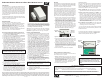
Location of
front and back
Tamper pill.
Slot for
ext. wire
entry.
Mounting
Holes
Back Page
Figure 2. ELK-6022 Sensor & Backplate
Alignment
Marks
Maximum
Operating
Gap = 1/2”
1/2”
Figure 1. ELK-6022 Mounting Gap and Alignment
4. If the case and back Tamper are used, remove the small
rubber tamper pill from the hardware bag and insert the
stem into the hollow post located in the center of the
baseplate. Gently push until it is firmly on the post.
5.
If using the external zones, strip and attach the wires to
the screw terminals marked IN1, COM, and IN3. The COM
is shared between both zones. Be careful when attaching
the sensor to the baseplate so the wires do not interfere
with the tamper or any other components. Make sure the
wires are not pinched.
6. Attach the sensor and magnet to their baseplates.