INSTALLATION MANUAL Cross Platform Control TM Part # ELK-M1EZ8 A member of the M1 Family Specifications, Installation and Programming M1 includes the SIA CP-01 Standards for False Alarm Reduction † L523 Rev. I 08/06/08 Current with Firmware 4.5.
Introduction LIMITATION This Control is designed to warn against unauthorized entry and other situations. However, it is not a guarantee of protection against the occurrence of burglary, fire, or other emergency. Any alarm system is subject to compromise or failure to warn for various reasons. For example: - Unauthorized access can be gained through unprotected points or by disarming or bypassing protected points. - Sensing devices are power driven and do not operate without electrical power.
Table of Contents Specifications, Features, and Benefits ..................................................................................................... 4 Wiring & Hookup Diagram ........................................................................................................................... 5 Section 1 - Installation and Wiring ............................................................................................................. 7 1.1 Planning the Installation .......................
Specifications, Features, and Benefits General: • Large zone capacity: 8 on-board zones expandable to 200 • Wireless capability: † Up to 48 zones • Two Way Listen-in interface † • Flash Memory - Allows field updates to firmware electronically • Time/Date stamped 512 event history log • Menu driven, text keypad programming • 12 On-Board Outputs: 1 siren driver/voltage, 1 form “C” Relay, and 10 low current (10 mA) voltage outputs • Total number of Rules Supported: 528 • Rules utilize easy to understand text
Wiring & Hookup Diagram Sealed Lead Acid Battery (ELK-1250) STATUS 12V Battery RED BLK BATTERY For Canada use cUL Listed Transformer - ATC Frost #FPS-4016 Power LED is ON when AC is present. Status LED:1 blink = Normal Operation. 2 fast blinks = Bootloader mode. 4 fast blinks = Initializing EEPROM memory. 5 fast blinks = Memory/Operation overflow. ELK PRODUCTS, INC. For Installation of Residential Fire Warning Systems reference CAN/ULC-S540 Standard.
Intentionally Left Blank Page 6 M1EZ8 Installation and Programming
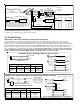
Section 1 - Installation and Wiring 1.1 Planning the Installation The first step in any multi-zone security system installation is planning the job. 1. Read this entire manual to familiarize yourself with all system features and procedures before actually beginning the installation. Read all the information regarding Underwriters Laboratories (UL) and NFPA requirements. 2. Perform a physical survey of the installation site. Use the diagrams below as a guide in planning the installation. 3.
Hookup Diagram for Keypad Splice 6 Pin Keypad Wiring Assembly to the Data Bus cable using ELK-900-2 "B" Connectors. BLACK WHITE GREEN RED BLUE BROWN Data Bus Cable CAT5 or CAT6 Recommended To Red (Pos) Wire To Brown Wire + - Keypad 1 1 6 To BROWN Wire Load (50mA max) i.e. Relay, LED See Note about Data Bus Termination ELK-M1KP Keypad Wiring Assembly To BLACK (Neg) Wire The optional Zone Input # or Output # is determined by the Keypad Address. + - Load (50mA max) I.E.
Two-Wire Smoke Zone (Zone 8) To enable use of two-wire smoke detectors position Jumper JP1 to the 2 wire smoke position. Go to Installer programming mode, Menu 05 - Zone Definitions, and program Zone 8 as a Fire zone (Def=10). Step to next location and program Wire Type=6. NOTE Use only compatible two-wire detectors listed on the front label of the control. Do not mix brands. The maximum number of detectors is also listed on the front label.
AC Failure, Low Battery, and Automatic Low Voltage Shutdown During an AC power failure the battery automatically takes over and AC Fail trouble annunciates at the keypad. The communicator can be programmed to report AC Fail to the Central Station after a time delay (see Menu 12, System Option 01). If the battery voltage falls below 11.2 VDC a Low Battery Trouble condition will occur. The communicator can be programmed to report Low Battery to the Central Station.
Data Bus E.O.L. Termination - VERY IMPORTANT! The control features a true RS-485 “differential” data bus operating at 38,400 bits per second. This is relatively high speed by industry standards and ensures fast, accurate communications. With this speed, EOL data bus terminating resistors are required to eliminate the possibility of reflection errors caused by varying cable lengths. Every data bus device; keypad, zone expander, etc.
The ELK-M1DBHR † "Active" Data Bus Hub Retrofit splits the Controls' main RS-485 Data Bus into 4 managed RS-485 branches. Each branch can have 2 parallel home run cables for a total of 8 home runs. The last (end of line) device on each home run should be jumper terminated to insure proper operation and supervision. ELK-M1DBHR † DATA BUS HUB FOR RETROFIT RED GREEN WHITE A BLACK B - INPUT FROM CONTROL + JP1 This diagram illustrates the M1DBHR Hub as a single branch on a Control.
Section 2 - Operating the System 2.1 Introduction The control has factory default programming which make it easy to bench test prior to installation. Terminate all zones with EOL resistors, then connect a keypad, transformer, and battery. The factory (Master) user code is 3456. This code can operate all user related features of the system. This section gives an overview of powering up and basic keypad functioning. 2.
2.5 Keypad Overview Ready Light - ON when all burglar zones are secure and the system is OK to arm. If OFF, one or more zones are violated (not secure). For maximum security, secure all zones before arming the system. If FLASHING, one or more force-armable zones are violated. Force arming temporarily excludes violated zone(s) from the system. If a force armed zone becomes secure while system is armed, it will automatically restore to service.
123456789012345678901234567890 123456789012345678901234567890 123456789012345678901234567890 123456789012345678901234567890 123456789012345678901234567890 READY TO ARM 123456789012345678901234567890 123456789012345678901234567890 123456789012345678901234567890 9:00AM 08/01/03 123456789012345678901234567890 123456789012345678901234567890 Keypad Menus The control offers extended Menu Options via the center navigation “ELK” key. Some menus may require a valid code to authorize.
123456789012345678901234567890 123456789012345678901234567890 123456789012345678901234567890 123456789012345678901234567890 123456789012345678901234567890 3-Walk Test Area r 123456789012345678901234567890 123456789012345678901234567890 123456789012345678901234567890 < Area? Name > 123456789012345678901234567890 123456789012345678901234567890 123456789012345678901234567890 123456789012345678901234567890 123456789012345678901234567890 123456789012345678901234567890 000of016 Tested r 12345678901234567890123456
123456789012345678901234567890 123456789012345678901234567890 123456789012345678901234567890 123456789012345678901234567890 84-System r 123456789012345678901234567890 123456789012345678901234567890 123456789012345678901234567890 Tests 123456789012345678901234567890 123456789012345678901234567890 123456789012345678901234567890 123456789012345678901234567890 123456789012345678901234567890 123456789012345678901234567890 123456789012345678901234567890 1:Battery Test r 123456789012345678901234567890 123456789012
123456789012345678901234567890 123456789012345678901234567890 123456789012345678901234567890 123456789012345678901234567890 123456789012345678901234567890 9-Installation r 123456789012345678901234567890 123456789012345678901234567890 123456789012345678901234567890 Programming (0) 123456789012345678901234567890 From this menu you may press the RIGHT arrow to enter Installation Level Programming. If the Installer Programming Code has not already been entered it will be required at this time.
Section 3 - Programming The Control 3.1 Introduction The Security functionality of the Control can be programmed either from an ELK-M1KP LCD Keypad, ELK-M1KP2 LCD Keypad, OR from the ELK-RP PC Software. The keypad features a menu-driven “Text” based interface with simple Yes/No answers for most options. After just a short amount of experience the average installer will not even require an instruction manual to keypad program the control.
3.5 Communicator Setup Checklist The Communicator (Dialer) can dial up to 8 phone numbers plus RP. Digital reporting formats include: Pulse 4+2, SIA, Contact ID, and Pager. Use the following checklist for each required telephone number. 1. 2. 3. 4. 5. 6.
M1EZ8 Installation and Programming Page 21 Menu 03 Area Defs Area 1 (1) Exit Delay 1 (2) Entry Delay 1 (3) Exit Delay 2 (4) Entry Delay 2 (5) Auto Stay (6) Exit Restart (7) Closing Ringback (8) SglKey Quickarm (9) DblKey Quickarm (10) StayKeyScroll (11) Stay Instant (12) Night Scroll (13) Night Instant (14) StayChgArmed (15) [Name] Menu 02 User Code Auth.
12345678901234567890123456789012123 12345678901234567890123456789012123 12345678901234567890123456789012123 12345678901234567890123456789012123 12345678901234567890123456789012123 12345678901234567890123456789012123 12345678901234567890123456789012123 12345678901234567890123456789012123 12345678901234567890123456789012123 12345678901234567890123456789012123 12345678901234567890123456789012123 01-Bus Module Enrollment r Menu 01 - Bus Module Enrollment Press RIGHT arrow key to select this menu.
12345678901234567890123456789012123 12345678901234567890123456789012123 12345678901234567890123456789012123 12345678901234567890123456789012123 12345678901234567890123456789012123 12345678901234567890123456789012123 12345678901234567890123456789012123 12345678901234567890123456789012123 12345678901234567890123456789012123 12345678901234567890123456789012123 12345678901234567890123456789012123 02-UserCode Optn Code used to: r Menu 02 - User Code Options Press RIGHT arrow key to select this menu.
12345678901234567890123456789012123 12345678901234567890123456789012123 12345678901234567890123456789012123 12345678901234567890123456789012123 12345678901234567890123456789012123 12345678901234567890123456789012123 12345678901234567890123456789012123 12345678901234567890123456789012123 12345678901234567890123456789012123 12345678901234567890123456789012123 12345678901234567890123456789012123 r 03-Area Definitions Menu 03 - Area Definitions Press RIGHT arrow key to select this menu.
Menu 03 - Area Definitions (continued) Area Definitions 12345678901234567890123456789012123 12345678901234567890123456789012123 12345678901234567890123456789012123 12345678901234567890123456789012123 12345678901234567890123456789012123 12345678901234567890123456789012123 12345678901234567890123456789012123 12345678901234567890123456789012123 12345678901234567890123456789012123 12345678901234567890123456789012123 12345678901234567890123456789012123 12345678901234567890123456789012123 A1 07:=No Sendr Closin
12345678901234567890123456789012123 12345678901234567890123456789012123 12345678901234567890123456789012123 12345678901234567890123456789012123 12345678901234567890123456789012123 12345678901234567890123456789012123 12345678901234567890123456789012123 12345678901234567890123456789012123 12345678901234567890123456789012123 12345678901234567890123456789012123 12345678901234567890123456789012123 04-Keypad Definitions r Keypad Definitions Menu 04 - Keypad Definitions Press RIGHT arrow key to select this men
Menu 04 - Keypad Definitions (continued) Keypad Definitions Description of Option 12345678901234567890123456789012123 12345678901234567890123456789012123 12345678901234567890123456789012123 To program the F1 key definitions press the right arrow key. The program will branch off 12345678901234567890123456789012123 12345678901234567890123456789012123 12345678901234567890123456789012123 into the 7 options for this key.
12345678901234567890123456789012123 12345678901234567890123456789012123 12345678901234567890123456789012123 12345678901234567890123456789012123 12345678901234567890123456789012123 12345678901234567890123456789012123 12345678901234567890123456789012123 12345678901234567890123456789012123 12345678901234567890123456789012123 12345678901234567890123456789012123 12345678901234567890123456789012123 05-Zone Definitions r Menu 05 - Zone Definitions Press RIGHT arrow key to select this menu.
Menu 05 - Zone Definitions (continued) Def Zone Description Operating Characteristics 15 † Keyfob - Used when a wireless keyfob is enrolled into a receiver at this zone ID location. 16 Non Alarm - Intended for use in Whenever/And/Then rules from the Remote Programming RP software. This zone type DOES NOT ACTIVATE any alarm and is not logged in the Event log. No reset is required. 17 †† Carbon Monoxide 24 hr - Activates an immediate Carbon Monoxide alarm if tripped anytime (armed or disarmed).
Menu 05 - Zone Definitions (continued) Zone Definitions 123456789012345678901234567890121234 123456789012345678901234567890121234 123456789012345678901234567890121234 123456789012345678901234567890121234 123456789012345678901234567890121234 123456789012345678901234567890121234 123456789012345678901234567890121234 123456789012345678901234567890121234 123456789012345678901234567890121234 123456789012345678901234567890121234 123456789012345678901234567890121234 ZN001 05: =Yes Dialer Delay r 123456789012345
12345678901234567890123456789012123 12345678901234567890123456789012123 12345678901234567890123456789012123 12345678901234567890123456789012123 12345678901234567890123456789012123 12345678901234567890123456789012123 12345678901234567890123456789012123 12345678901234567890123456789012123 12345678901234567890123456789012123 12345678901234567890123456789012123 12345678901234567890123456789012123 06-Alarm Cutoff Timers r Menu 06 - Alarm Duration Timers Press RIGHT arrow key to select this menu.
12345678901234567890123456789012123 12345678901234567890123456789012123 12345678901234567890123456789012123 12345678901234567890123456789012123 12345678901234567890123456789012123 12345678901234567890123456789012123 12345678901234567890123456789012123 12345678901234567890123456789012123 12345678901234567890123456789012123 12345678901234567890123456789012123 12345678901234567890123456789012123 07-Global System r Definitions Global Sys Definitions 123456789012345678901234567890121234 1234567890123456789012
Menu 07 - Global System Definitions (continued) Global Sys Definitions 12345678901234567890123456789012123 12345678901234567890123456789012123 12345678901234567890123456789012123 12345678901234567890123456789012123 12345678901234567890123456789012123 12345678901234567890123456789012123 12345678901234567890123456789012123 12345678901234567890123456789012123 12345678901234567890123456789012123 12345678901234567890123456789012123 12345678901234567890123456789012123 G13:_ _ _ _ _ _ _ _r Common To Area1 12345
Menu 07 - Global System Definitions (continued) Global Sys Definitions 123456789012345678901234567890121234 123456789012345678901234567890121234 123456789012345678901234567890121234 123456789012345678901234567890121234 123456789012345678901234567890121234 123456789012345678901234567890121234 123456789012345678901234567890121234 123456789012345678901234567890121234 123456789012345678901234567890121234 123456789012345678901234567890121234 123456789012345678901234567890121234 G28:=No Out2 r SingleAlmLockout
Menu 07 - Global System Definitions (continued) Global Sys Def 12345678901234567890123456789012123 12345678901234567890123456789012123 12345678901234567890123456789012123 12345678901234567890123456789012123 12345678901234567890123456789012123 12345678901234567890123456789012123 12345678901234567890123456789012123 12345678901234567890123456789012123 12345678901234567890123456789012123 12345678901234567890123456789012123 12345678901234567890123456789012123 12345678901234567890123456789012123 G38:=No Xmitr T
12345678901234567890123456789012123 12345678901234567890123456789012123 12345678901234567890123456789012123 12345678901234567890123456789012123 12345678901234567890123456789012123 12345678901234567890123456789012123 12345678901234567890123456789012123 12345678901234567890123456789012123 12345678901234567890123456789012123 12345678901234567890123456789012123 12345678901234567890123456789012123 08-Telephone r Account Setup Telephone Acct Setup 123456789012345678901234567890121234 12345678901234567890123456
Menu 08 Telephone Account Setup (continued) Telephone Acct Setup Description of Option 12345678901234567890123456789012123 12345678901234567890123456789012123 12345678901234567890123456789012123 12345678901234567890123456789012123 12345678901234567890123456789012123 12345678901234567890123456789012123 12345678901234567890123456789012123 12345678901234567890123456789012123 12345678901234567890123456789012123 12345678901234567890123456789012123 12345678901234567890123456789012123 T1: 08:=000000r Acct # for
12345678901234567890123456789012123 12345678901234567890123456789012123 12345678901234567890123456789012123 12345678901234567890123456789012123 12345678901234567890123456789012123 12345678901234567890123456789012123 12345678901234567890123456789012123 12345678901234567890123456789012123 12345678901234567890123456789012123 12345678901234567890123456789012123 12345678901234567890123456789012123 09-Area Reporting Codes r Menu 09 - Area Reporting Codes Press RIGHT arrow key to select this menu.
Menu 09 - Area Reporting Codes (continued) Area Report Codes 12345678901234567890123456789012123 12345678901234567890123456789012123 12345678901234567890123456789012123 12345678901234567890123456789012123 12345678901234567890123456789012123 12345678901234567890123456789012123 12345678901234567890123456789012123 12345678901234567890123456789012123 12345678901234567890123456789012123 12345678901234567890123456789012123 12345678901234567890123456789012123 AR1 11:Code= 00r Duress Code 12345678901234567890123
12345678901234567890123456789012123 12345678901234567890123456789012123 12345678901234567890123456789012123 12345678901234567890123456789012123 12345678901234567890123456789012123 12345678901234567890123456789012123 12345678901234567890123456789012123 12345678901234567890123456789012123 12345678901234567890123456789012123 12345678901234567890123456789012123 12345678901234567890123456789012123 10-Zone Reportng Codes r Menu 10 - Zone Reporting Codes Press RIGHT arrow key to select this menu.
12345678901234567890123456789012123 12345678901234567890123456789012123 12345678901234567890123456789012123 12345678901234567890123456789012123 12345678901234567890123456789012123 12345678901234567890123456789012123 12345678901234567890123456789012123 12345678901234567890123456789012123 12345678901234567890123456789012123 12345678901234567890123456789012123 12345678901234567890123456789012123 11-Keypad F-Keyr Reporting Codes Menu 11 - Keypad F-Key Reporting Codes Press RIGHT arrow key to select this menu.
12345678901234567890123456789012123 12345678901234567890123456789012123 12345678901234567890123456789012123 12345678901234567890123456789012123 12345678901234567890123456789012123 12345678901234567890123456789012123 12345678901234567890123456789012123 12345678901234567890123456789012123 12345678901234567890123456789012123 12345678901234567890123456789012123 12345678901234567890123456789012123 12-Sys Rpt Code r Options & Codes Menu 12 - Sys Report Code Options & Codes Press RIGHT arrow key to select this m
Menu 12 - Sys Report Code Options & Codes (continued) Sys Rpt Code Options 12345678901234567890123456789012123 12345678901234567890123456789012123 12345678901234567890123456789012123 12345678901234567890123456789012123 12345678901234567890123456789012123 12345678901234567890123456789012123 12345678901234567890123456789012123 12345678901234567890123456789012123 12345678901234567890123456789012123 12345678901234567890123456789012123 12345678901234567890123456789012123 SR11: T=00 R=00 r Low Battery 12345678
12345678901234567890123456789012123 12345678901234567890123456789012123 12345678901234567890123456789012123 12345678901234567890123456789012123 12345678901234567890123456789012123 12345678901234567890123456789012123 12345678901234567890123456789012123 12345678901234567890123456789012123 12345678901234567890123456789012123 12345678901234567890123456789012123 12345678901234567890123456789012123 13-User Codes Report r Menu 13 - User Report Codes Press RIGHT arrow key to select this menu.
12345678901234567890123456789012123 12345678901234567890123456789012123 12345678901234567890123456789012123 12345678901234567890123456789012123 12345678901234567890123456789012123 12345678901234567890123456789012123 12345678901234567890123456789012123 12345678901234567890123456789012123 12345678901234567890123456789012123 12345678901234567890123456789012123 12345678901234567890123456789012123 14-Wireless Definitions r Menu 14 - Wireless Definitions † Press RIGHT arrow key to select this menu.
1234567890123456789012345678901212345 1234567890123456789012345678901212345 1234567890123456789012345678901212345 1234567890123456789012345678901212345 1234567890123456789012345678901212345 1234567890123456789012345678901212345 1234567890123456789012345678901212345 1234567890123456789012345678901212345 1234567890123456789012345678901212345 1234567890123456789012345678901212345 1234567890123456789012345678901212345 123456789012345678901234567890121234 123456789012345678901234567890121234 12345678901234567890
Section 4 - PC Programming and Automation Capabilities 4.1 ELK-RP Software ELK-RP (RP) is a Windows based software package that is compatible with Windows 98 and later. It features an extremely intuitive user interface and contains all data in a central database. RP can be run on a single PC or over a local area network (LAN) with multiple operators. In addition to the traditional security programming features, RP allows you to create and manage the automation functionality in the control.
4.1.2 Check for Conflicts During the connect and disconnect process RP performs an automatic check of the data stored in the control and compares it the database. If there are any conflicts (differences), a pop-up resolution window display them and allows corrections to be made. ELK regards “Check for Conflicts” to be an especially important feature. It can point out any changes that have occurred such as a user having added or changed a code.
4.3 Automation Rules and Attributes The RP Automation Programming software offers powerful, easy to setup and manage, life style enhancement features. The automation programming allows mixing and matching of lighting components, outputs (relays or voltage), thermostats, temperature sensors, and all the security inputs and features to integrate functions that add value and appeal to the owner/ user.
† LIGHTING - The control can handle up to 256 Light (or appliance) devices. Each is assigned to one of 256 addresses. Each device is displayed in a column format with the following options and settings: Name - Each device can be given a 16 character name (description) which is displayed on the keypad when the light is being controlled. Format - This pull down box selects the protocol of the device. The available Lighting formats are: Standard, Extended, Preset dim, Compose, Serial Port.
CUSTOM SETTINGS - These are 20 memory locations which may be assigned a 12 character description, a function type (one of 3), and a starting value. An authorized user can then access the custom settings from keypad user menu 7Automation Custom Settings, and modify the value whether it be a numeric value, a timer (seconds), or a time-of-day. Incorporating custom settings in rules provides the user the ability to modify how the rule will operate.
TEXTS - This section allows custom text messages to be constructed and formatted. These messages can be transmitted to an LCD keypad or out one of the RS232 serial ports to a PC or some other type of equipment. A message to the keypad could be “Happy Birthday” or “Please Pay Your Bill”, while a message going out a serial port might be a series of ASCII characters formatted to a certain manufacturers protocol.
RULES - This section essentially brings all the power of the control’s automation and its features together. Rules consist of three major elements: A WHENEVER (“triggering”) condition, one or more ANDs (“qualifiers”), and one or more THENs (“activations”). Rules utilize the various elements of the previously described sections in addition to the many control conditions (arm, disarm, alarms, etc.), plus many of the event codes listed in Appendix A.
AND - The second and optional element of a rule is a qualifier. Rules can have one or more qualifiers OR none at all. Even though qualifiers are not required, they are ideal for filtering out actions that should not occur under certain circumstances. A qualifier can be a time, day(s), the state of light or dark, the state of a zone, output, or light, and hundreds of other variables. The state of light or dark can be determined by the Sunrise/Sunset settings from the M1’s Astronomical Clock.
Examples of Rules - Shown below are a series of rules that should help illustrate the power and results that rules can provide. Look closely at the ones that have multiple ANDs and THENs. Rules with Multiple ANDs and THENS work as follows: When the WHENEVER element is triggered, each one of the AND elements is evaluated to determine if the condition its testing is true. If any one of the ANDs are not true, the rule engine stops executing the rule immediately.
Appendix A - Event Codes Event Codes are four digit numbers used to represent alarms, troubles, arm/disarms, restores, and various other conditions that occur within the control. For the most part, they are used only internally by the control’s software. For example: turning on the alarm output. However, there are cases where the installer may need these codes. Case #1 - Keypad F key programming. Each of the Keypad F keys may be programmed to activate a particular condition such as Emergency Panic Alarm.
Appendix A - Event Codes (cont.
Appendix B & C - Unused [Intentionally left blank] Page 58 M1EZ8 Installation and Programming
[Intentionally left blank] M1EZ8 Installation and Programming Page 59
Appendix D - Two Way “Listen-in/Talk” Interface † Using a Two Way Interface board (ELK-EZ8TWI), up to 3 zones of listen-in can be provided. Each zone can have up to 4 microphones for a total of 12 listen-in points. Talk back is delivered through the speakers connected to the EZ8TWI. A two way session can be triggered by any number of zones when an alarm occurs. Two way can also be triggered during a Telephone Remote Control session. Instructions for the ELK-EZ8TWI are included with the interface.
Appendix E - SIA CP-01 Compliance † This control has been self-verified to be compliant with the SIA CP-01 Control Panel Standard - Features for False Alarm Reduction PROGRAMMABLE FEATURES, SHIPPING DEFAULTS, AND RECOMMENDED PROGRAMMING FEATURE CP-01 Std. Par. # REQUIREMENT ALLOWABLE RANGE / PURPOSE RECOMMENDED PROGRAMMING * SHIPPING DEFAULT Exit Delay Time 1 & Exit Delay Time 2 4.2.2.1 Required (programmable) 45 - 120 sec.
Appendix F - Unused [Intentionally left blank] Page 62 M1EZ8 Installation and Programming
Appendix F - Unused [Intentionally left blank] M1EZ8 Installation and Programming Page 63
Appendix F - Unused [Intentionally left blank] † Not evaluated by UL Page 64 M1EZ8 Installation and Programming
Appendix G - Additional ELK-M1KP Keypad Information OPTIONAL PLUG-IN PROX CARD READER † (Internal or external on ELK-M1KP, external only on ELK-M1KP2) Prox cards/fobs are enrolled into a User Code location using the same procedures used to add/change User Code PINs. 1. Press the ELK key, then press the 6 key (or scroll up) to display 6 - Change User Codes. Press the RIGHT arrow key to select this menu. A Master user code (PIN) must be entered to gain access to this menu. 2.
M1 LIMITED WARRANTY The ELK-M1EZ8 and its associated component products are warranted by Elk Products, Inc. (“Manufacturer”) against defects in material and workmanship for a period of two (2) years from the date of manufacture. If product is found to be defective during the first 180 days, manufacturer may allow an over the counter exchange, subject to inspection and approval by one of it’s representatives.
Index A I S Alarm Abort 38 Alarm Cutoff Timers 31 Anti-Takeover 19 Area Partitioning 19 Area Reporting Codes 38, 39 Auto Stay Option 25 Automation control function 15 Automation Tasks 49 Auxiliary Power Connections 9 Input/Output Expander Addresses 22 Installation and Wiring 7 Installer Program Code 13, 15, 19, 20, 23 Serial Port Baud Rate 35 SIA CP-01 Compliance - Appendix E 61 Silent Alarm 29 SingleAlmLockout 35 Specifications, Features, and Benefits 4 Sunrise/Sunset 50 SwingerShutdown 31 Sys Rpt Cod
www.elkproducts.